PRE-CRASH SAFETY SYSTEM Pre-crash Safety System Circuit
WIRING DIAGRAM
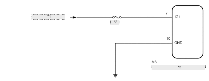
| *1 | from IG1 NO.1 Relay |
| *2 | GAUGE |
| *3 | Pre-crash Safety City Sensor |
CAUTION / NOTICE / HINT
Note
-
Inspect the fuses for circuits related to this system before performing the following procedure.
-
When replacing the pre-crash safety city sensor, replace it with a new one. If an ECU which was installed to another vehicle is used, the information stored in the pre-crash safety city sensor will not match the information from the vehicle and, as a result, a DTC may be output.
-
When the pre-crash safety city sensor is replaced with a new one or it is removed, camera beam axis learning must be performed.
PROCEDURE
-
CUSTOMER PROBLEM ANALYSIS AND SYMPTOM CHECK
-
Check the customer problem analysis and symptom Click here.
NEXT 
-
-
INSPECT AUXILIARY BATTERY VOLTAGE
-
Measure the auxiliary battery voltage.
Standard voltage 11 to 14 V (IG OFF) -
Using the parts location and system diagram, check the system for blown-out fuses, open or short circuits in the wire harness(es) and connectors that are not properly connected by performing a visual check.
Tech Tips
If the voltage is 11 V or less, replace or recharge the auxiliary battery before proceeding to the next step.
NEXT
-
-
CHECK HARNESS AND CONNECTOR
-
Check pre-crash safety city sensor.
Note
DTCs may be output when connectors are disconnected during inspection. Therefore, make sure to clear the DTCs using the GTS once the inspection has been completed.
-
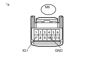
Text in Illustration *a Front view of wire harness connector
(to Pre-crash Safety City Sensor)
Disconnect the pre-crash safety city sensor connector.
-
Measure the voltage according to the value(s) in the table below.
Standard Voltage Tester Connection Switch Condition Specified Condition M6-7 (IG1) - Body ground Ignition switch ON (IG) 11 to 14 V M6-7 (IG1) - Body ground Ignition switch off Below 1 V -
Measure the resistance according to the value(s) in the table below.
Standard Resistance Tester Connection Condition Specified Condition M6-10 (GND) - Body ground Always Below 1 Ω
-
NG 
REPAIR OR REPLACE HARNESS OR CONNECTOR
OK
-
-
CHECK CAN COMMUNICATION SYSTEM
-
Use the GTS to check if the CAN communication system is functioning normally Click here.
Result Result Proceed to CAN communication system DTCs are not output A CAN communication system DTCs are output B
B 
CHECK FOR DTCs (CHECK OUTPUT OF METER/GAUGE SYSTEM DTC U023A) Click here
A
-
-
CHECK FOR DTCs
-
Check for DTCs and note any codes that are output Click here.
-
Clear the DTCs Click here.
-
Recheck for DTCs. Try to reproduce the DTCs by duplicating the conditions indicated by the DTCs. Click here.
Result Result Proceed to DTCs are not output A DTCs are output B
A
PROCEED TO NEXT SUSPECTED AREA SHOWN IN PROBLEM SYMPTOMS TABLE Click here
B
GO TO DIAGNOSTIC TROUBLE CODE CHART Click here
-
-
CHECK FOR DTCs (CHECK OUTPUT OF METER/GAUGE SYSTEM DTC U023A)
-
Connect the GTS to the DLC3.
-
Turn the ignition switch to ON.
-
Turn the GTS on.
-
Enter the following menus: Body Electrical / Combination Meter / Trouble Codes.
-
Check for DTCs Click here.
Result Result Proceed to Past DTC U023A is output A Present DTC U023A is output B
A
GO TO CAN COMMUNICATION SYSTEM Click here
B
-
-
READ VALUE USING GTS
-
Using the GTS, read the Data List Click here.
PCS/LDA/RSA/LVN Tester Display Measurement Item/Range Normal Condition Diagnostic Note Low Temperature Status Displays whether there is a low temperature malfunction / ON or OFF ON: Pre-crash safety city sensor low temperature malfunction exists
OFF: Pre-crash safety city sensor low temperature malfunction does not exist
- High Temperature Status Displays whether there is a high temperature malfunction / ON or OFF ON: Pre-crash safety city sensor high temperature malfunction exists
OFF: Pre-crash safety city sensor high temperature malfunction does not exist
- Result Result Proceed to Temperature malfunction exists A Temperature malfunction does not exist B
B
GO TO CAN COMMUNICATION SYSTEM Click here
A
-
-
RETURN PRE-CRASH SAFETY CITY SENSOR TEMPERATURE TO NORMAL
-
Return the temperature of the pre-crash safety city sensor to normal.
NEXT
-
-
CHECK FOR DTCs
-
Check for DTCs and note any codes that are output Click here.
-
Clear the DTCs Click here.
-
Recheck for DTCs. Try to reproduce the DTCs by duplicating the conditions indicated by the DTCs Click here.
Result Result Proceed to DTCs are not output A DTCs are output B
B
GO TO DIAGNOSTIC TROUBLE CODE CHART Click here
A
-
-
CHECK DATA LIST / ACTIVE TEST
-
Using the GTS, check the Data List Click here.
-
Using the GTS, perform the Active Test Click here.
NEXT
PROCEED TO NEXT SUSPECTED AREA SHOWN IN PROBLEM SYMPTOMS TABLE Click here
-