PRE-CRASH SAFETY SYSTEM, Diagnostic DTC:C1A4B
| DTC Code | DTC Name |
|---|---|
| C1A4B | Stop Light Relay Circuit |
DESCRIPTION
The brake booster with master cylinder assembly (skid control ECU) outputs a stop light signal to the stop light switch assembly. When the brake booster with master cylinder assembly (skid control ECU) detects a malfunction relating to the stop light circuit, the pre-crash safety city sensor is notified via CAN communication, and C1A4B is output.
| DTC Code | DTC Detection Condition | Trouble Area |
|---|---|---|
| C1A4B |
|
|
-
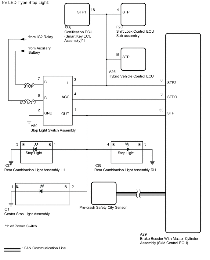
*1: for LED Type Stop Light
-
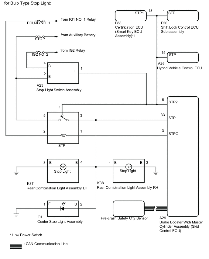
*2: for Bulb Type Stop Light
WIRING DIAGRAM
CAUTION / NOTICE / HINT
Note
-
When this DTC is output, a malfunction in the lighting system is suspected. Check if the lighting system is functioning normally.
-
Inspect the fuses for circuits related to this system before performing the following procedure.
-
When replacing the pre-crash safety city sensor, replace it with a new one and be sure to initialize the settings. If an ECU which was installed to another vehicle is used, the information stored in the pre-crash safety city sensor will not match the information from the vehicle and, as a result, a DTC may be output.
-
If the pre-crash safety city sensor has been replaced, or the windshield glass has been replaced or removed/installed, be sure to perform Recognition Camera/Target Position Memory and Recognition Camera Axis Adjust.
-
First check the CAN communication system by following How to Proceed with Troubleshooting. After checking that there are no malfunctions in the CAN communication system, proceed to troubleshooting.
-
Perform adjustment using "ONE TIME RECOGNITION" or "SEQUENTIAL RECOGNITION".
-
ONE TIME RECOGNITION
-
SEQUENTIAL RECOGNITION
PROCEDURE
-
CHECK STOP LIGHT OPERATION
-
Check that the stop lights come on when the brake pedal is depressed and go off when the brake pedal is released.
OK The stop lights illuminate when the brake pedal is depressed. The stop lights turn off when the brake pedal is released. Result Result Proceed to NG A OK (for LED Type Stop Light) B OK (for Bulb Type Stop Light) C
A 
GO TO LIGHTING SYSTEM Click here
C 
INSPECT NO. 4 RELAY BLOCK (POWER SOURCE TERMINAL) Click here
B 
-
-
CHECK HARNESS AND CONNECTOR (POWER SOURCE TERMINAL)
-
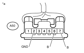
Text in Illustration *a Front view of wire harness connector
(to Stop Light Switch Assembly)
Disconnect the stop light switch assembly connector.
-
Measure the voltage according to the value(s) in the table below.
Standard Voltage Tester Connection Switch Condition Specified Condition A50-7 (B) - Body ground Ignition switch off 11 to 14 V A50-6 (B) - Body ground Ignition switch ON 11 to 14 V -
Measure the resistance according to the value(s) in the table below.
Standard Resistance Tester Connection Condition Specified Condition A50-2 (GND) - Body ground Always Below 1 Ω
NG
REPAIR OR REPLACE HARNESS OR CONNECTOR
OK
-
-
CHECK HARNESS AND CONNECTOR (STP TERMINAL)
-
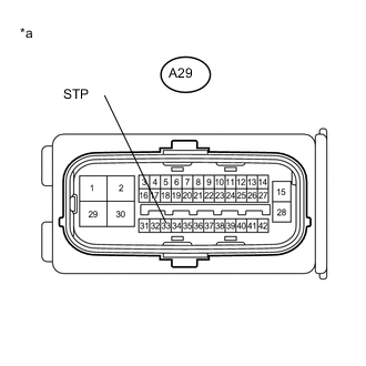
Text in Illustration *a Front view of wire harness connector
(to Brake Booster With Master Cylinder Assembly [Skid Control ECU])
Disconnect the brake booster with master cylinder assembly (skid control ECU) connector.
-
Measure the voltage according to the value(s) in the table below.
Standard Voltage Tester Connection Condition Specified Condition A29-33 (STP) - Body ground Brake pedal depressed 11 to 14 V A29-33 (STP) - Body ground Brake pedal released Below 1.5 V
NG
REPAIR OR REPLACE HARNESS OR CONNECTOR
OK
-
-
PERFORM ACTIVE TEST USING GTS (STOP LIGHT RELAY)
-
Enter the following menus: Chassis / ABS/VSC/TRC / Active Test.
-
Perform "Active Test" according to the display on GTS.
ABS/VSC/TRC Tester Display Test Part Control Range Diagnostic Note Stop Light Relay Switches stop light on/off ON/OFF Possible at vehicle speed of 0 km/h (0 mph) -
Enter the following menus: Chassis / ABS/VSC/TRC / Data List.
-
Check the stop light switch assembly operation using the Data List and stop light operation by performing an Active Test.
ABS/VSC/TRC Tester Display Measurement Item/Range Normal Condition Diagnostic Note Stop Light Relay Output STPO terminal output condition / ON or OFF ON: Stop light switch assembly output on (Stop light on)
OFF: Stop light switch assembly output off (Stop light off)
- Result Result Proceed to Data List item changes between ON and OFF, but stop lights do not turn on A Data List item changes between ON and OFF and stop lights turn on and off B
B
CHECK HARNESS AND CONNECTOR (BRAKE BOOSTER WITH MASTER CYLINDER ASSEMBLY [SKID CONTROL ECU] - STOP LIGHT SWITCH ASSEMBLY) Click here
A
-
-
CHECK HARNESS AND CONNECTOR (BRAKE BOOSTER WITH MASTER CYLINDER ASSEMBLY [SKID CONTROL ECU] - STOP LIGHT SWITCH ASSEMBLY)
-
Disconnect the A29 brake booster with master cylinder assembly (skid control ECU) connector.
-
Disconnect the A50 stop light switch assembly connector.
-
Measure the resistance according to the value(s) in the table below.
Standard Resistance Tester Connection Condition Specified Condition A29-3 (STPO) - A50-4 (ACC) Always Below 1 Ω A29-3 (STPO) - Body ground Always 10 kΩ or higher
NG
REPAIR OR REPLACE HARNESS OR CONNECTOR
OK
-
-
CHECK HARNESS AND CONNECTOR (BRAKE BOOSTER WITH MASTER CYLINDER ASSEMBLY [SKID CONTROL ECU] - STOP LIGHT SWITCH ASSEMBLY)
-
Disconnect the A29 brake booster with master cylinder assembly (skid control ECU) connector.
-
Disconnect the A50 stop light switch assembly connector.
-
Disconnect the A26 hybrid vehicle control ECU connector.
-
Disconnect the F20 shift lock control ECU sub-assembly connector.
-
Disconnect the F88 certification ECU (smart key ECU assembly)*1 connector.
-
Measure the resistance according to the value(s) in the table below.
-
*1: w/ Power Switch
Standard Resistance Tester Connection Condition Specified Condition A29-6 (STP2) - A50-3 (L) Always Below 1 Ω A29-6 (STP2) - Body ground Always 10 kΩ or higher -
NG
REPAIR OR REPLACE HARNESS OR CONNECTOR
OK
-
-
CHECK HARNESS AND CONNECTOR (STP TERMINAL)
-
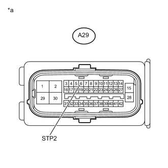
Text in Illustration *a Front view of wire harness connector
(to Brake Booster With Master Cylinder Assembly [Skid Control ECU])
Disconnect the brake booster with master cylinder assembly (skid control ECU) connector.
-
Measure the voltage according to the value(s) in the table below.
Standard Voltage Tester Connection Condition Specified Condition A29-6 (STP2) - Body ground Brake pedal depressed 11 to 14 V A29-6 (STP2) - Body ground Brake pedal released Below 1.5 V
NG
REPLACE STOP LIGHT SWITCH ASSEMBLY Click here
OK
-
-
CHECK FOR DTCs
-
Clear the DTCs Click here.
-
Make sure that the DTC detection conditions are met.
Tech Tips
-
If the detection conditions are not met, the system cannot detect the malfunction.
-
Using the GTS, perform the Active Test "Stop Light Relay" with the ignition switch ON.
-
-
Check for DTCs Click here.
Result Result Proceed to DTC C1A4B is not output A DTC C1A4B is output B
A
USE SIMULATION METHOD TO CHECK Click here
B
REPLACE PRE-COLLISION CITY SENSOR Click here
-
-
INSPECT NO. 4 RELAY BLOCK (POWER SOURCE TERMINAL)
-
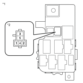
Text in Illustration *1 No. 4 Relay Block *2 Stop Light Relay (STP Relay) Measure the voltage according to the value(s) in the table below.
Standard Voltage Tester Connection Switch Condition Specified Condition Stop light control relay (STP relay) terminal 5 - Body ground Ignition switch off 11 to 14 V Stop light control relay (STP relay) terminal 2 - Body ground Ignition switch ON (IG) 11 to 14 V
NG
REPAIR OR REPLACE HARNESS OR CONNECTOR (POWER SOURCE CIRCUIT)
OK
-
-
CHECK HARNESS AND CONNECTOR (STP TERMINAL)
-
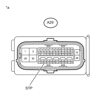
Text in Illustration *a Front view of wire harness connector
(to Brake Booster With Master Cylinder Assembly (Skid Control ECU))
Disconnect the brake booster with master cylinder assembly (Skid Control ECU) connector.
-
Measure the voltage according to the value(s) in the table below.
Standard Voltage Tester Connection Switch Condition Specified Condition A29-33(STP) - Body ground Brake pedal depressed 8 to 14 V A29-33(STP) - Body ground Brake pedal released Below 1.5 V
NG
REPAIR OR REPLACE HARNESS OR CONNECTOR
OK
-
-
PERFORM ACTIVE TEST USING GTS (STOP LIGHT RELAY)
-
Enter the following menus: Chassis / ABS/VSC/TRC / Active Test.
-
Perform "Active Test" according to the display on GTS.
ABS/VSC/TRC Tester Display Measurement Item Control Range Diagnostic Note Stop Light Relay Stop light relay (STP relay) ON or OFF Stop lights come on -
Enter the following menus: Chassis / ABS/VSC/TRC / Data List.
-
Check the Data List for proper functioning of the stop light control relay (STP relay).
ABS/VSC/TRC Tester Display Measurement Item Range Control Range Diagnostic Note Stop Light Relay Output Stop light relay (STP relay) output ON or OFF ON: Relay output on (Stop light on)
OFF: Relay output off (Stop light off)
- Result Result Proceed to Data List content and stop light operation are abnormal or Data List content is normal but stop lights do not turn on or off. A Data List content and stop light operation are normal. B
B
INSPECT STOP LIGHT RELAY (STP RELAY) Click here
A
-
-
CHECK HARNESS AND CONNECTOR (BRAKE BOOSTER WITH MASTER CYLINDER ASSEMBLY [SKID CONTROL ECU] - STOP LIGHT SWITCH ASSEMBLY)
-
Disconnect the A29 brake booster with master cylinder assembly (skid control ECU) connector.
-
Remove the stop light relay (STP relay).
-
Measure the resistance according to the value(s) in the table below.
Standard Resistance Tester Connection Condition Specified Condition A29-3 (STPO) - Stop light control relay (STP relay) terminal 1 Always Below 1 Ω A29-3 (STPO) - Body ground Always 10 kΩ or higher
NG
REPAIR OR REPLACE HARNESS OR CONNECTOR
OK
-
-
INSPECT STOP LIGHT RELAY (STP RELAY)
-
Turn the ignition switch off.
-
Remove the stop light relay (STP relay).
-
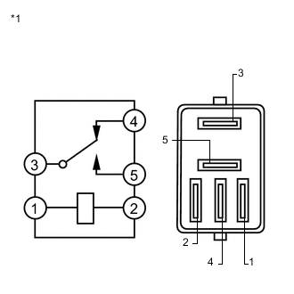
Text in Illustration *1 Stop Light Relay (STP Relay) Measure the resistance according to the value(s) in the table below.
Standard Resistance Tester Connection Condition Specified Condition 3 - 4 Voltage is not applied between terminals 1 and 2 Below 1 Ω 3 - 5 Voltage is not applied between terminals 1 and 2 10 kΩ or higher 3 - 4 Voltage is applied between terminals 1 and 2 10 kΩ or higher 3 - 5 Voltage is applied between terminals 1 and 2 Below 1 Ω
NG
REPLACE STOP LIGHT RELAY (STP RELAY)
OK
-
-
CHECK HARNESS AND CONNECTOR (BRAKE BOOSTER WITH MASTER CYLINDER ASSEMBLY [SKID CONTROL ECU] - STOP LIGHT SWITCH ASSEMBLY)
-
Disconnect the A29 brake booster with master cylinder assembly (skid control ECU) connector.
-
Disconnect the A23 stop light switch assembly connector.
-
Disconnect the A26 hybrid vehicle control ECU connector.
-
Disconnect the F20 shift lock control ECU sub-assembly connector.
-
Disconnect the F88 certification ECU (smart key ECU assembly)*1 connector.
-
Remove the stop light relay (STP relay).
-
Measure the resistance according to the value(s) in the table below.
-
*1: w/ Power Switch
Standard Resistance Tester Connection Condition Specified Condition A29-6 (STP2) - Stop light control relay (STP relay) terminal 4 Always Below 1 Ω A29-6 (STP2) - Body ground Always 10 kΩ or higher -
NG
REPAIR OR REPLACE HARNESS OR CONNECTOR
OK
-
-
CHECK HARNESS OR CONNECTOR (STP2 TERMINAL)
-
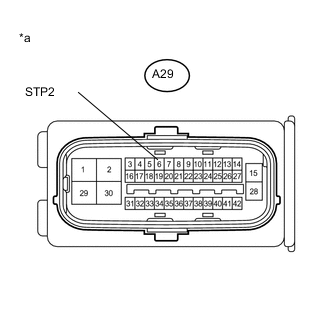
Text in Illustration *a Front view of wire harness connector
(to Brake Booster With Master Cylinder Assembly (Skid Control ECU))
Disconnect the brake booster with master cylinder assembly (Skid Control ECU) connector.
-
Turn the ignition switch to ON.
-
Measure the voltage according to the value(s) in the table below.
Standard Voltage Tester Connection Switch Condition Specified Condition A29-6 (STP2) - Body ground Brake pedal depressed 11 to 14 V A29-6 (STP2) - Body ground Brake pedal released Below 1.5 V
NG
REPAIR OR REPLACE HARNESS OR CONNECTOR (STP2 CIRCUIT)
OK
-
-
CHECK FOR DTCs
-
Clear the DTCs Click here.
-
Make sure that the DTC detection conditions are met.
Tech Tips
-
If the detection conditions are not met, the system cannot detect the malfunction.
-
Using the GTS, perform the Active Test "Stop Light Relay" with the ignition switch ON.
-
-
Check for DTCs Click here.
Result Result Proceed to DTC C1A4B is not output A DTC C1A4B is output B
A
USE SIMULATION METHOD TO CHECK Click here
B
REPLACE PRE-COLLISION CITY SENSOR Click here
-