SPIRAL CABLE INSTALLATION
CAUTION / NOTICE / HINT
CAUTION:
Some of these service operations affect the SRS airbag system. Read the precautionary notices concerning the SRS airbag system before servicing Click here.
PROCEDURE
-
INSPECT SPIRAL CABLE WITH SENSOR SUB-ASSEMBLY
Note
If the spiral cable with sensor sub-assembly is installed with the center position misaligned, steering angle sensor value abnormal DTCs will be stored, and recovery will be impossible. In this case, replace the spiral cable with sensor sub-assembly with a new one.
-
Check the spiral cable with sensor sub-assembly center position.
Standard Connector is at the highest point. Alignment marks are aligned. Colored roller or top of flat cable U-turn portion can be seen through the check window. 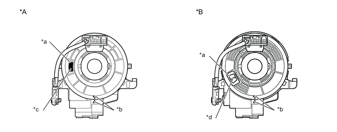
*A Colored Roller Visible Type *B Flat Cable Visible Type *a Check Window *b Alignment Marks *c Colored Roller *d Top of U-turn Portion of Flat Cable -
If the spiral cable with sensor sub-assembly is not at the center position, perform centering of the spiral cable with sensor sub-assembly.
Note
Failure to observe the following precautions could result in breakage of the spiral cable with sensor sub-assembly.
-
Do not hold the airbag connector or wiring when rotating the spiral cable with sensor sub-assembly.
-
Do not rotate with excessive force.
-
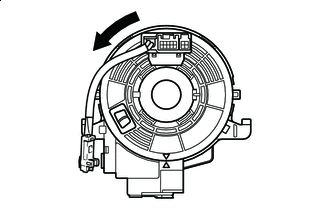

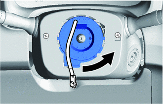
Rotation Direction Making sure to rotate in the counterclockwise direction only, slowly rotate the spiral cable with sensor sub-assembly in the counterclockwise direction until it stops.
Note
Make sure to rotate in the counterclockwise direction only. Rotating in the clockwise direction can break the spiral cable with sensor sub-assembly or make centering impossible.
-
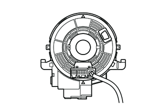
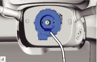
When the rotation stops, if the connector has passed the lowermost position, return the connector to the lowermost position as shown in the illustration.
-
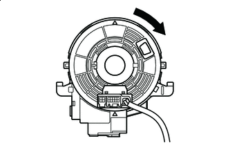
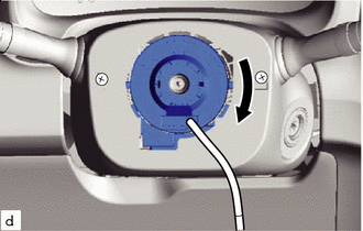
Rotation Direction Rotate the spiral cable swith sensor sub-assembly back in the clockwise direction for approximately 2.5 turns so that the connector moves from the lowermost position to the topmost position.
Note
With the connector in the lowermost position, rotating clockwise 5 turns or more could break the spiral cable with sensor sub-assembly.
-
Check that the spiral cable with sensor sub-assembly is centered.
Standard Connector is at the highest point. Alignment marks are aligned. Colored roller or top of flat cable U-turn portion can be seen through the check window.
*A Colored Roller Visible Type *B Flat Cable Visible Type *a Check Window *b Alignment Marks *c Colored Roller *d Top of U-turn Portion of Flat Cable Note
If centering cannot be achieved, the spiral cable with sensor sub-assembly may be broken, so replace it with a new one.
-
-
-
INSTALL SPIRAL CABLE WITH SENSOR SUB-ASSEMBLY
-
Check that the ignition switch is turned off.
-
Check that the negative auxiliary battery terminal is detached.
CAUTION:
Wait at least 90 seconds after disconnecting the cable from the negative (-) auxiliary battery terminal to disable the SRS system.
-
Check that the front tires face straight forward.
-
Check that the turn signal switch is in the neutral position.
Note
Perform the operation when the turn signal switch is in the neutral position. Otherwise, the turn signal pin will break.
-
Engage the 3 claws to install the spiral cable with sensor sub-assembly.
Note
Pull the lock pin out before installing the steering wheel when replacing the spiral cable with sensor sub-assembly with a new one.
-
Connect the steering sensor connector.
-
Connect the airbag connector.
-
Connect the horn connector.
-
-
INSTALL UPPER STEERING COLUMN COVER
-
INSTALL LOWER STEERING COLUMN COVER
-
INSTALL STEERING COLUMN COVER SUPPORT (w/ Entry and Start System)
-
ADJUST SPIRAL CABLE
-
Check that the ignition switch is turned off.
-
Check that the cable is disconnected from the negative (-) auxiliary battery terminal.
CAUTION:
Wait at least 90 seconds after disconnecting the cable from the negative (-) auxiliary battery terminal to disable the SRS system.
-
Confirm that the front tires face straight forward.
-
Check the spiral cable center position.
Standard Connector is at the highest point. Colored roller or top of flat cable U-turn portion can be seen through the check window. 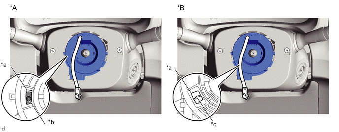
*A Colored Roller Visible Type *B Flat Cable Visible Type *a Check Window *b Colored Roller *c Top of U-turn Portion of Flat Cable - - -
If the spiral cable is not at the center position, perform centering of the spiral cable.
Note
Failure to observe the following precautions could result in breakage of the spiral cable.
-
Do not rotate the spiral cable while the negative (-) battery cable is connected and the ignition switch is turned to ON.
-
Do not hold the airbag connector or wiring when rotating the spiral cable.
-
Do not rotate with excessive force.
-
Rotation Direction Making sure to rotate in the counterclockwise direction only, slowly rotate the spiral cable in the counterclockwise direction until it stops.
Note
Make sure to rotate in the counterclockwise direction only. Rotating in the clockwise direction can break the spiral cable or make centering impossible.
-
When the rotation stops, if the connector has passed the lowermost position, return the connector to the lowermost position as shown in the illustration.
-
Rotation Direction Rotate the spiral cable back in the clockwise direction for approximately 2.5 turns so that the connector moves from the lowermost position to the topmost position.
Note
With the connector in the lowermost position, rotating clockwise 5 turns or more could break the spiral cable.
-
Check that the spiral cable is centered.
Standard Connector is at the highest point. Colored roller or top of flat cable U-turn portion can be seen through the check window.
*A Colored Roller Visible Type *B Flat Cable Visible Type *a Check Window *b Colored Roller *c Top of U-turn Portion of Flat Cable - - Note
If centering cannot be achieved, the spiral cable may be broken, so replace it with a new one.
-
-
-
INSTALL STEERING WHEEL ASSEMBLY
-
INSTALL STEERING PAD
-
CONNECT CABLE TO NEGATIVE AUXILIARY BATTERY TERMINAL
- Torque:
- 5.4 N*m { 55 kgf*cm, 48 in.*lbf }
Note
When disconnecting the cable, some systems need to be initialized after the cable is reconnected Click here.
-
INSTALL FRONT FLOOR COVER RH (for Front Floor Cover Type A)
-
INSTALL FRONT FLOOR COVER RH (for Front Floor Cover Type B)
-
INSTALL CENTER FRONT FLOOR COVER (for Front Floor Cover Type B)
-
INSPECT SRS WARNING LIGHT