METER / GAUGE SYSTEM TERMINALS OF ECU
-
CHECK COMBINATION METER ASSEMBLY
-
Disconnect the F1 and F2 combination meter assembly connector.
-
Measure the voltage and resistance of the wire harness side connector.
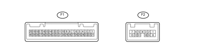
Terminals No. (Symbol) Wiring Color Terminal Description Condition Specified Condition F1-21 (ET) - Body ground W-B - Body ground Ground Always Below 1 Ω F1-39 (IG+) - Body ground P - Body ground Ignition switch signal Ignition switch off → ON (IG) Below 1 V → 11 to 14 V F1-40 (B) - Body ground L - Body ground Battery Always 11 to 14 V F2-1 (B) - Body ground R - Body ground Battery Always 11 to 14 V If the result is not as specified, there may be a malfunction in the wire harness.
-
Reconnect the F1 and F2 combination meter assembly connector.
-
Measure the voltage, resistance and check for pulses of the wire harness side connector.
Terminals No. (Symbol) Wiring Color Terminal Description Condition Specified Condition F1-1 (RLMT) - Body ground GR - Body ground Rear LH seat belt warning light signal Rear LH seat belt warning light ON → OFF Below 1 V → 11 to 14 V F1-2 (RCMT) - Body ground G - Body ground Rear CENTER seat belt warning light signal Rear CENTER seat belt warning light ON → OFF Below 1 V → 11 to 14 V F1-3 (RRMT) - Body ground B - Body ground Rear RH seat belt warning light signal Rear RH seat belt warning light ON → OFF Below 1 V → 11 to 14 V F1-5 (SI) - Body ground L - Body ground Speed signal (Input) Driving at approximately
20 km/h (12 mph)
Pulse generation
(See waveform 1)
F1-6 (+S) - Body ground SB - Body ground Speed signal (Output) Driving at approximately
20 km/h (12 mph)
Pulse generation
(See waveform 1)
F1-7 (P/SB) - Body ground P - Body ground Front seat inner belt assembly signal (passenger side) Front passenger seat is occupied and its seat belt is unfastened → fastened Below 1 V → 11 to 14 V F1-9 (S) - Body ground Y - Body ground Engine oil pressure signal Engine oil pressure warning light ON → OFF Below 1 V → 11 to 14 V F1-11 (CHK) - Body ground LG - Body ground Check engine warning light signal Check engine warning light ON → OFF Below 1 V → 11 to 14 V F1-14 (-) - Body ground W-B - Body ground High beam indicator signal (-) Always Below 1 V F1-16 (L) - Body ground G - Body ground Fuel level signal Ignition switch ON (IG)
Fuel level is FULL → EMPTY
Below 1 V → 4.5 to 9.0 V F1-19 (+) - Body ground GR - Body ground High beam indicator signal (+) High beam indicator ON → OFF 11 to 14 V → Below 1 V F1-20 (ILL+) - Body ground R - Body ground Taillight signal Light control switch off → on Below 1 V → 11 to 14 V F1-24 (RLSB) - Body ground V - Body ground Rear seat inner belt assembly signal (LH side) Rear LH seat belt is unfastened → fastened Below 1 V → 11 to 14 V F1-25 (RCSB) - Body ground R - Body ground Rear seat inner belt assembly signal (Center side) Rear CENTER seat belt is unfastened → fastened Below 1 V → 11 to 14 V F1-26 (RRSB) - Body ground BE - Body ground Rear seat inner belt assembly signal (RH side) Rear RH seat belt is unfastened → fastened Below 1 V → 11 to 14 V F1-31 (CANL) - Body ground W - Body ground CAN communication line Ignition switch ON (IG) Pulse generation F1-32 (CANH) - Body ground G - Body ground CAN communication line Ignition switch ON (IG) Pulse generation F2-3 (HAZ) - Body ground L - Body ground Hazard warning signal switch signal Hazard warning signal switch off 11 to 14 V Hazard warning signal switch on Below 1 Ω F2-6 (TAIL) - Body ground LG - Body ground Taillight signal Light control switch off → on Below 1 V → 11 to 14 V F2-7 (LR) - Body ground V - Body ground Right turn signal Ignition switch ON (IG)
Right turn indicator light OFF → ON
Below 1 V → 11 to 14 V F2-9 (ER) - Body ground B - Body ground Turn signal switch RH signal Turn signal switch RH on Below 1 V Turn signal switch RH off 11 to 14 V F2-10 (EL) - Body ground Y - Body ground Turn signal switch LH signal Turn signal switch LH on Below 1 V Turn signal switch LH off 11 to 14 V F2-11 (S) - Body ground SB - Body ground Rear fog signal Ignition switch ON (IG)
Rear fog switch off → on
Below 1 V → 11 to 14 V F2-12 (FOG)*1 - Body ground BE - Body ground Front fog signal Ignition switch ON (IG)
Front fog switch off → on
Below 1 V → 11 to 14 V F2-13 (LL) - Body ground LG - Body ground Left turn signal Ignition switch ON (IG)
Left turn indicator light OFF → ON
Below 1 V → 11 to 14 V
-
*1: w/ Fog Light
If the result is not as specified, the combination meter assembly may have a malfunction.
-
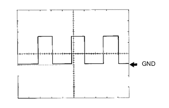
Waveform 1: Using an oscilloscope
Terminal Connections F1-6 (+S) - Body ground
F1-5 (SI) - Body ground
Tool Setting 5 V/DIV., 20 ms./DIV. Condition Driving at approximately 20 km/h (12 mph) Tech Tips
As the vehicle speed increases, the cycle of the signal waveform narrows.
-
-
-
CHECK MAIN BODY ECU (MULTIPLEX NETWORK BODY ECU) AND INSTRUMENT PANEL JUNCTION BLOCK ASSEMBLY
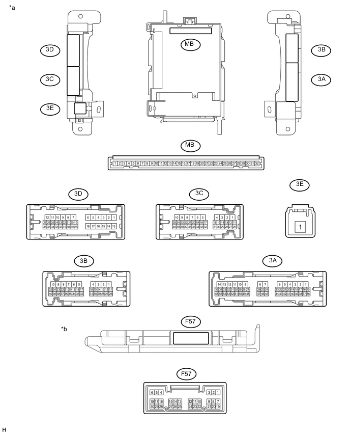
Text in Illustration *a Instrument Panel Junction Block Assembly *b Main Body ECU
(Multiplex Network Body ECU)
-
Remove the main body ECU (multiplex network body ECU) Click here.
-
Measure the resistance and voltage between each terminal of the wire harness side connectors and body ground.
Terminal No. (Symbol) Wiring Color Terminal Description Condition Specified Condition MB-11 (GND1) - Body ground None - Body ground Ground Always Below 1 Ω MB-29 (ACC) - Body ground None - Body ground Ignition power supply (ACC signal) Ignition switch ACC 11 to 14 V MB-30 (BECU) - Body ground None - Body ground +B (power system signal system) power supply Always 11 to 14 V MB-32 (IG) - Body ground None - Body ground Ignition power supply (IG signal) Ignition switch ON (IG) 11 to 14 V If the result is not as specified, there may be a malfunction on the wire harness side.
-
Install the main body ECU (multiplex network body ECU).
-
Measure the voltage between each terminal of the wire harness side connectors and body ground.
Terminal No. (Symbol) Wiring Color Terminal Description Condition Specified Condition 3A-28 (PKB) - Body ground R - Body ground Parking brake signal Parking brake warning light ON → OFF Below 1 V → 11 to 14 V 3D-34 (DBKL) - Body ground W - Body ground Front seat inner belt assembly signal (driver side) Driver seat belt warning light OFF → ON Below 1 V → 11 to 14 V F57-13 (CANL) - Body ground W - Body ground CAN communication line Ignition switch ON (IG) Pulse generation F57-14 (CANH) - Body ground R - Body ground CAN communication line Ignition switch ON (IG) Pulse generation If the result is not as specified, there may be a malfunction in the wire harness.
-
-
COMBINATION METER INTERNAL CIRCUIT
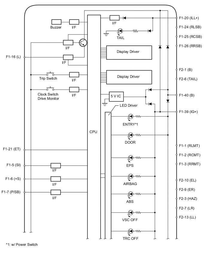
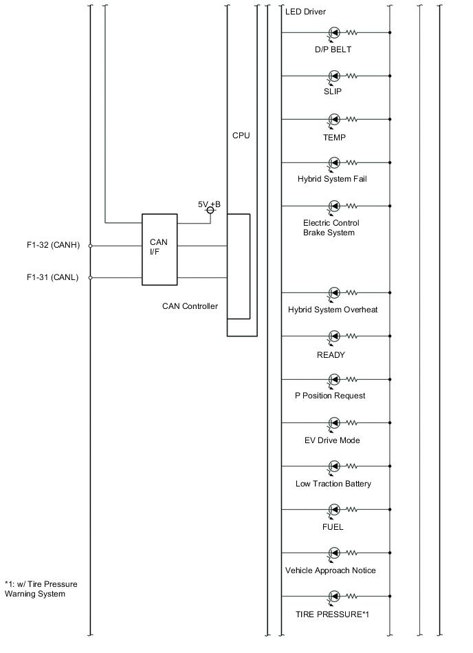
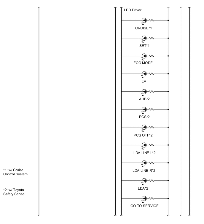
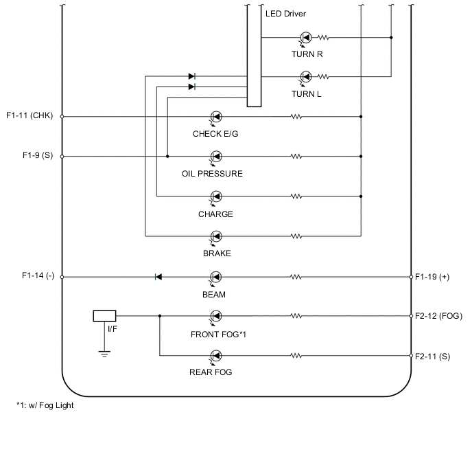
Connectors Terminal No. Wire Harness Side F1 1 Telltale light assembly (Rear Seat LH) 2 Telltale light assembly (Rear Seat CENTER) 3 Telltale light assembly (Rear Seat RH) 5 Brake booster with master cylinder assembly (skid control ECU) 6 Other ECU 7 Occupant detection sensor and Front seat inner belt assembly (Front passenger side) 9 Engine oil pressure switch assembly 11 ECM 14 Body ground 16 Fuel sender gauge assembly 19 H-LP LH HI fuse 20 Panel fuse 21 Body ground 24 Rear seat inner belt assembly LH 25 Rear seat inner belt assembly CENTER 26 Rear seat inner belt assembly RH 31 CAN communication line 32 CAN communication line 39 IG2 relay 40 Auxiliary battery F2 1 Auxiliary battery 3 Telltale light assembly 6 Panel fuse 7 Turn signal light RH 9 Headlight dimmer switch assembly (Turn signal switch) 10 Headlight dimmer switch assembly (Turn signal switch) 11 FOG RR relay 12 FOG FR relay*1 13 Turn signal light LH
-
*1: w/ Fog Light
-