ENGINE IMMOBILISER SYSTEM(w/o Power Switch) Power Source Mode does not Change to ON (READY)
DESCRIPTION
The key ID code of the transponder chip inside the IG key is compared against the key ID code registered in the transponder key ECU assembly. While checking the code, the transponder key ECU assembly supplies electrical power to the transponder chip in the key by means of the transponder key coil. If the codes match, the immobiliser is then UNSET (released), and after the hybrid control system start permission signal is sent to the power management control ECU, if communication is functioning properly, hybrid control system start can be performed.
Tech Tips
-
When the key is inserted into the ignition key cylinder, the transponder key coil receives the key code and outputs it to the transponder key ECU assembly.
-
If this symptom occurs, there may be a communication problem between the transponder key coil and the transponder key ECU assembly.
WIRING DIAGRAM
Refer to "System Diagram" Click here.
CAUTION / NOTICE / HINT
Note
-
When replacing the key and transponder key ECU assembly, refer to Service Bulletin.
-
Inspect the fuses for circuits related to this system before performing the following inspection procedure.
PROCEDURE
-
CLEAR DTC
-
Clear the DTCs Click here.
NEXT 
-
-
CHECK FOR DTC
-
Check for DTCs Click here.
Tech Tips
Before checking for DTCs, perform the "DTC Output Confirmation Operation" procedure.
Result Result Proceed to No DTC output A DTC output B
B 
GO TO DIAGNOSTIC TROUBLE CODE CHART Click here
A
-
-
READ VALUE USING GTS (PERMIT START BY IMMOBILISER)
-
Turn the ignition switch off.
-
Connect the GTS to the DLC3.
-
Turn the ignition switch to ON.
-
Turn the GTS on.
-
Enter the following menus: Powertrain / Hybrid Control / Data List.
Hybrid Control Tester Display Measurement Item/Range Normal Condition Diagnostic Note Permit Start by Immobiliser Status of the permit start by Immobiliser / Abnoml, No Chk, Check, Norml or Ini Cnd - - OK The item in the Data List indicates "Normal". Result Result Proceed to NG A OK B
B
GO TO HYBRID CONTROL SYSTEM Click here
A
-
-
READ VALUE USING GTS (IMMOBILISER)
-
Turn the ignition switch off.
-
Connect the GTS to the DLC3.
-
Turn the ignition switch to ON.
-
Turn the GTS on.
-
Enter the following menus: Body Electrical / Immobiliser / Data List.
Immobiliser Tester Display Measurement Item/Range Normal Condition Diagnostic Note Immobiliser Engine immobiliser system status determined by transponder key ECU assembly /
Set or Unset
Set: Engine immobiliser set (hybrid control system start prohibited (no key in ignition key cylinder))
Unset: Engine immobiliser unset (hybrid control system start permitted (key inserted in ignition key cylinder))
When the engine immobiliser system does not change to the unset state, this item can be used to determine if the cause is the transponder key ECU assembly. OK The item in the Data List indicates "Unset". Result Result Proceed to NG A OK B
B 
CHECK WHETHER HYBRID CONTROL SYSTEM STARTS Click here
A
-
-
READ VALUE USING GTS (IMMOBILISER)
-
Perform inspection using a different key that has been registered to the vehicle.
-
Turn the ignition switch off.
-
Connect the GTS to the DLC3.
-
Turn the ignition switch to ON.
-
Turn the GTS on.
-
Enter the following menus: Body Electrical / Immobiliser / Data List.
Immobiliser Tester Display Measurement Item/Range Normal Condition Diagnostic Note Immobiliser Engine immobiliser system status determined by transponder key ECU assembly / Set or Unset Set: Engine immobiliser set ((hybrid control system start prohibited (no key in ignition key cylinder))
Unset: Engine immobiliser unset ((hybrid control system start permitted (key inserted in ignition key cylinder))
When the engine immobiliser system does not change to the unset state, this item can be used to determine if the cause is the transponder key ECU assembly. OK The item in the Data List indicates "Unset".
NG
REPLACE TRANSPONDER KEY COIL Click here
OK
-
-
CHECK WHETHER HYBRID CONTROL SYSTEM STARTS WITH OTHER KEYS
-
Perform inspection using a different key that has been registered to the vehicle.
OK Hybrid control system starts normally.
OK
END (KEY MALFUNCTION)
NG
INSPECT POWER MANAGEMENT CONTROL ECU (TERMINAL IMI) Click here
-
-
CHECK WHETHER HYBRID CONTROL SYSTEM STARTS
-
Turn the ignition switch to ON, wait for 5 seconds, then start the hybrid control system.
OK Hybrid control system starts normally.
OK
END
NG
-
-
INSPECT POWER MANAGEMENT CONTROL ECU (TERMINAL IMI)
-
Using an oscilloscope, check the waveform.
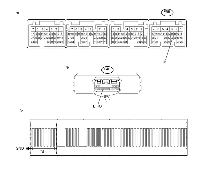
Text in Illustration *a Component with harness connected
(Power Management Control ECU)
*b Component with harness connected
(Transponder Key ECU Assembly)
*c Waveform 1 *d Waveform A Measurement Condition Item Content Tester Connection F56-21 (IMI) - F40-13 (EFIO) Tool Setting 2 V/DIV., 500 ms./DIV. Condition Within 3 seconds after hybrid control system starts, or within 3 seconds after ignition switch first turned to ON after auxiliary battery disconnected and reconnected OK Waveform is output normally (refer to illustration). Result Result Proceed to Normal waveform A Waveform 1 (Waveform A) not output, or has abnormal wavelength or shape B
B
CHECK HARNESS AND CONNECTOR (TRANSPONDER KEY ECU ASSEMBLY - POWER MANAGEMENT CONTROL ECU) Click here
A
-
-
INSPECT POWER MANAGEMENT CONTROL ECU (TERMINAL IMO)
-
Using an oscilloscope, check the waveform.
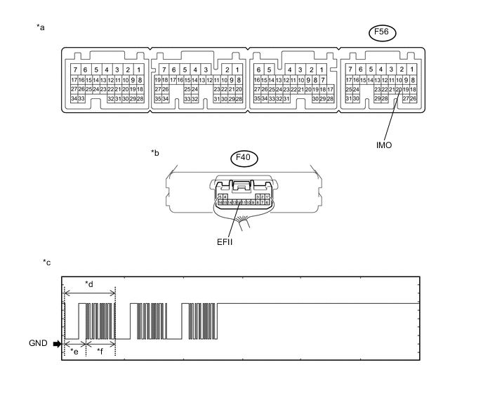
Text in Illustration *a Component with harness connected
(Power Management Control ECU)
*b Component with harness connected
(Transponder Key ECU Assembly)
*c Waveform 1 *d Waveform A *e 160 ms *f 270 ms Measurement Condition Item Content Tester Connection F56-20 (IMO) - F40-12 (EFII) Tool Setting 2 V/DIV., 500 ms./DIV. Condition Within 3 seconds after hybrid control system starts, or within 3 seconds after ignition switch first turned to ON after auxiliary battery disconnected and reconnected OK Waveform is output normally (refer to illustration). Result Result Proceed to Normal waveform A Waveform 1 (Waveform A) not output, or has abnormal wavelength or shape B
B
REPLACE POWER MANAGEMENT CONTROL ECU Click here
A
-
-
INSPECT POWER MANAGEMENT CONTROL ECU (TERMINAL IMI)
-
Using an oscilloscope, check the waveform.
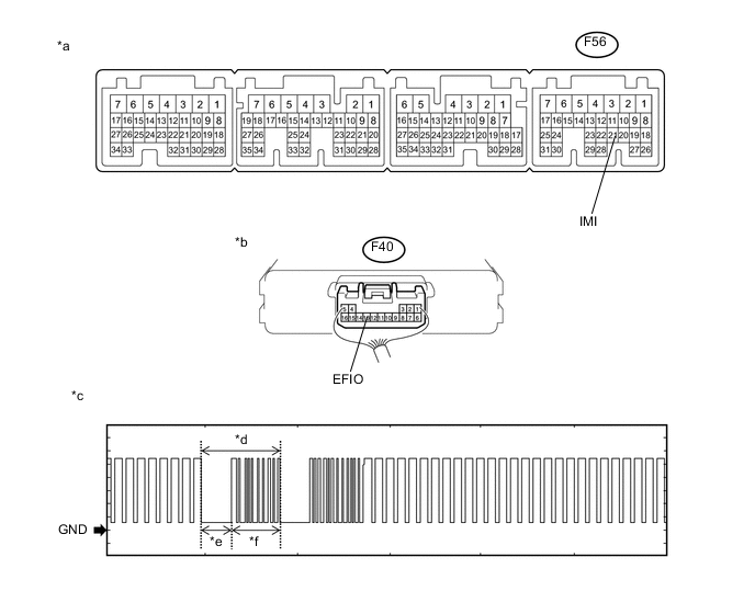
Text in Illustration *a Component with harness connected
(Power Management Control ECU)
*b Component with harness connected
(Transponder Key ECU Assembly)
*c Waveform 1 *d Waveform A *e 160 ms *f 270 ms Measurement Condition Item Content Tester Connection F56-21 (IMI) - F40-13 (EFIO) Tool Setting 2 V/DIV., 500 ms./DIV. Condition Within 3 seconds after hybrid control system starts, or within 3 seconds after ignition switch first turned to ON after auxiliary battery disconnected and reconnected OK Waveform is output normally (refer to illustration). Result Result Proceed to Normal waveform A Waveform 1 (Waveform A) not output, or has abnormal wavelength or shape B
B
REPLACE TRANSPONDER KEY ECU ASSEMBLY Click here
A
-
-
REGISTER ECU COMMUNICATION ID
-
Register the ECU communication ID (Refer to Service Bulletin).
NEXT
-
-
CHECK WHETHER HYBRID CONTROL SYSTEM STARTS
-
Check that the hybrid control system starts with the key.
OK Hybrid control system starts normally.
OK
END
NG
REPLACE TRANSPONDER KEY ECU ASSEMBLY Click here
-
-
CHECK HARNESS AND CONNECTOR (TRANSPONDER KEY ECU ASSEMBLY - POWER MANAGEMENT CONTROL ECU)
-
Disconnect the F40 transponder key ECU assembly connector.
-
Disconnect the F56 power management control ECU connector.
-
Measure the resistance according to the value(s) in the table below.
Standard Resistance Tester Connection Condition Specified Condition F40-13 (EFIO) - F56-21 (IMI) Always Below 1 Ω F40-13 (EFIO) or F56-21 (IMI) - Body ground Always 10 kΩ or higher
NG
REPAIR OR REPLACE HARNESS OR CONNECTOR
OK
-
-
REPLACE TRANSPONDER KEY ECU ASSEMBLY
-
Replace the transponder key ECU assembly with a new one (Refer to Service Bulletin).
NEXT
-
-
REGISTER KEY
-
Register the key (Refer to Service Bulletin).
NEXT
-
-
REGISTER ECU COMMUNICATION ID
-
Register the ECU communication ID (Refer to Service Bulletin).
NEXT
-
-
CHECK WHETHER HYBRID CONTROL SYSTEM STARTS
-
Check that the hybrid control system starts with the key.
OK Hybrid control system starts normally.
OK
END (TRANSPONDER KEY ECU ASSEMBLY WAS DEFECTIVE)
NG
GO TO HYBRID CONTROL SYSTEM Click here
-
-
REPLACE TRANSPONDER KEY COIL
-
Replace the transponder key coil (Refer to Click here).
NEXT
-
-
CHECK WHETHER HYBRID CONTROL SYSTEM STARTS
-
Check that the hybrid control system starts with an already registered vehicle key.
OK Hybrid control system starts normally.
OK
END (TRANSPONDER KEY COIL WAS DEFECTIVE)
NG
-
-
REPLACE TRANSPONDER KEY ECU ASSEMBLY
-
Replace the transponder key ECU assembly with a new one (Refer to Service Bulletin).
NEXT
-
-
REGISTER KEY
-
Reregister the key (Refer to Service Bulletin).
NEXT
-
-
REGISTER ECU COMMUNICATION ID
-
Register the ECU communication ID (Refer to Service Bulletin).
NEXT
-
-
CHECK WHETHER HYBRID CONTROL SYSTEM STARTS
-
Check that the hybrid control system starts with the key.
OK Hybrid control system starts normally.
OK
END (TRANSPONDER KEY ECU ASSEMBLY WAS DEFECTIVE)
NG
-
-
REPLACE KEY
-
Replace the transponder key master transmitter with a new one (Refer to Service Bulletin).
NEXT
-
-
REREGISTER KEY
-
Reregister the key (Refer to Service Bulletin).
NEXT
-
-
CHECK WHETHER HYBRID CONTROL SYSTEM STARTS
-
Check that the hybrid control system starts with an already registered vehicle key.
OK Hybrid control system starts normally.
OK
END (TRANSPONDER KEY MASTER TRANSMITTER WAS DEFECTIVE)
NG
GO TO HYBRID CONTROL SYSTEM Click here
-