ENGINE IMMOBILISER SYSTEM(w/o Power Switch), Diagnostic DTC:B2796
| DTC Code | DTC Name |
|---|---|
| B2796 | No Communication in Immobiliser System |
DESCRIPTION
-
DTC B2796 is stored when a key is inserted into the ignition key cylinder but no communication occurs between the key and transponder key ECU assembly.
| DTC Code | DTC Detection Condition | Trouble Area | DTC Output Confirmation Operation |
|---|---|---|---|
| B2796 | The key code cannot be transmitted (1 trip detection logic*). |
|
Insert the key into the ignition key cylinder. |
-
*: Only output while a malfunction is present.
| Vehicle Condition when Malfunction Detected | Fail-safe Operation when Malfunction Detected |
|---|---|
| Hybrid control system cannot be started | - |
| DTC Code | Data List and Active Test |
|---|---|
| B2796 | Response |
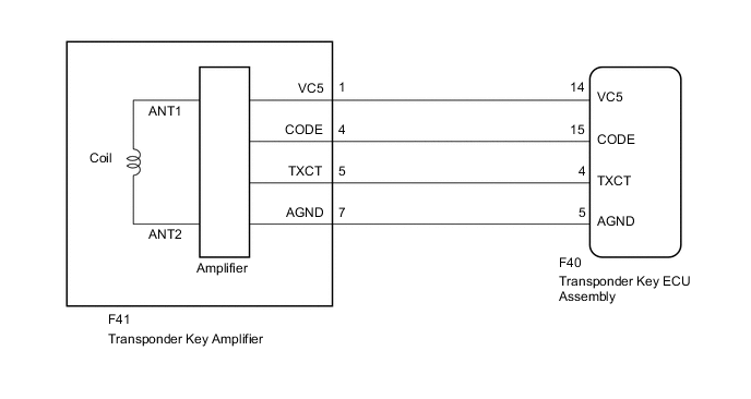
WIRING DIAGRAM
CAUTION / NOTICE / HINT
Note
-
When replacing the transponder key ECU assembly or key, refer to Service Bulletin.
-
After performing repairs, perform the operation that fulfills the DTC output confirmation operation, and then confirm that no DTCs are output again.
PROCEDURE
-
CLEAR DTC
-
Clear the DTCs Click here.
NEXT 
-
-
CHECK FOR DTC
-
Insert and remove each registered key one at a time, and check for DTC each time Click here.
Tech Tips
-
Before checking for DTCs, perform the "DTC Output Confirmation Operation" procedure.
-
If DTC B2796 is stored, check for DTCs with the next key after clearing the DTCs.
OK DTC B2796 is not output. Result Result Proceed to OK A NG (all keys) B NG (any key) C -
A 
USE SIMULATION METHOD TO CHECK Click here
C
REPLACE KEY THAT CANNOT START ENGINE
B
-
-
CHECK CONNECTION OF CONNECTOR
-
Check the connection of the transponder key ECU assembly and transponder key amplifier connectors.
-
Visually inspect the terminals of the transponder key ECU assembly and transponder key amplifier connectors.
OK Connectors are properly connected.
NG
CONNECT CONNECTORS PROPERLY
OK
-
-
CHECK WHETHER HYBRID CONTROL SYSTEM STARTS
-
Check that the hybrid control system starts with an already registered vehicle key.
OK Hybrid control system starts normally.
NG 
CHECK TRANSPONDER KEY AMPLIFIER Click here
OK
-
-
CLEAR DTC
-
Clear the DTCs Click here.
NEXT
-
-
CHECK FOR DTC
-
Check for DTCs Click here.
Tech Tips
Before checking for DTCs, perform the "DTC Output Confirmation Operation" procedure.
OK DTC B2796 is not output.
OK
END (CONNECTOR WAS NOT PROPERLY CONNECTED)
NG
-
-
CHECK TRANSPONDER KEY AMPLIFIER
-
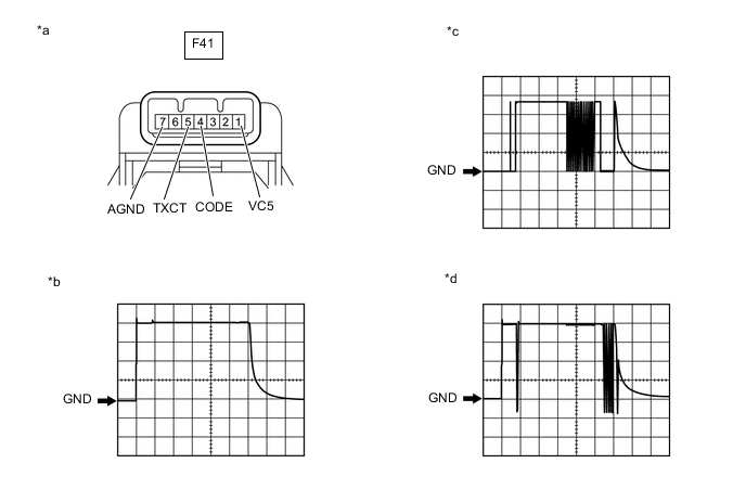
Using an oscilloscope, check the waveform.
-
Waveform 1 (Reference)
Measurement Condition Item Content Tester Connection F41-1 (VC5) - Body ground Tool Setting 1 V/DIV., 20 ms./DIV. Condition Key inserted in ignition key cylinder -
Waveform 2 (Reference)
Measurement Condition Item Content Tester Connection F41-5 (TXCT) - Body ground Tool Setting 1 V/DIV., 20 ms./DIV. Condition Key inserted in ignition key cylinder -
Waveform 3 (Reference)
Measurement Condition Item Content Tester Connection F41-4 (CODE) - Body ground Tool Setting 1 V/DIV., 20 ms./DIV. Condition Key inserted in ignition key cylinder OK Waveform is output normally (refer to illustration). Text in Illustration *a Component with harness connected
(Transponder Key Amplifier)
*b Waveform 1 *c Waveform 2 *d Waveform 3 Result Result Proceed to OK A NG (Waveform 1) B NG (Waveform 2) C NG (Waveform 3) (Stuck high (5V)) D NG (Waveform 3) (Stuck low (1 V or less)) E
-
A
REPLACE TRANSPONDER KEY ECU ASSEMBLY
C
CHECK TRANSPONDER KEY AMPLIFIER (TXCT) Click here
D
CHECK TRANSPONDER KEY AMPLIFIER (CODE) Click here
E
CHECK HARNESS AND CONNECTOR (TRANSPONDER KEY AMPLIFIER - TRANSPONDER KEY ECU ASSEMBLY) Click here
B
-
-
CHECK TRANSPONDER KEY AMPLIFIER (VC5)
-
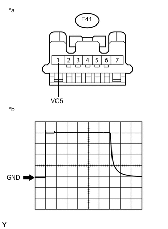
Text in Illustration *a Front view of wire harness connector
(to Transponder Key Amplifier)
*b Waveform Using an oscilloscope, check the waveform.
-
Waveform (Reference)
Measurement Condition Item Content Tester Connection F41-1 (VC5) - Body ground Tool Setting 1 V/DIV., 20 ms./DIV. Condition Key inserted in ignition key cylinder OK Waveform is output normally (refer to illustration).
-
OK
REPLACE TRANSPONDER KEY AMPLIFIER Click here
NG
-
-
CHECK HARNESS AND CONNECTOR (TRANSPONDER KEY AMPLIFIER - TRANSPONDER KEY ECU ASSEMBLY)
-
Disconnect the F41 transponder key amplifier connector.
-
Disconnect the F40 transponder key ECU assembly connector.
-
Measure the resistance according to the value(s) in the table below.
Standard Resistance Tester Connection Condition Specified Condition F41-1 (VC5) - F40-14 (VC5) Always Below 1 Ω F41-7 (AGND) - F40-5 (AGND) Always Below 1 Ω F41-1 (VC5) - Body ground Always 10 kΩ or higher -
Reconnect the transponder key amplifier connector.
-
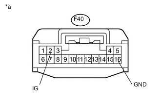
Measure the voltage according to the value(s) in the table below.
Standard Voltage Tester Connection Condition Specified Condition F40-2 (IG) - F40-16 (GND) Ignition switch ON 11 to 14 V
OK
REPLACE TRANSPONDER KEY ECU ASSEMBLY
NG
REPAIR OR REPLACE HARNESS OR CONNECTOR
-
-
CHECK TRANSPONDER KEY AMPLIFIER (TXCT)
-
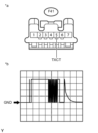
Text in Illustration *a Front view of wire harness connector
(to Transponder Key Amplifier)
*b Waveform Using an oscilloscope, check the waveform.
-
Waveform (Reference)
Measurement Condition Item Content Tester Connection F41-5 (TXCT) - Body ground Tool Setting 1 V/DIV., 20 ms./DIV. Condition Key inserted in ignition key cylinder OK Waveform is output normally (refer to illustration).
-
OK
REPLACE TRANSPONDER KEY AMPLIFIER Click here
NG
-
-
CHECK HARNESS AND CONNECTOR (TRANSPONDER KEY AMPLIFIER - TRANSPONDER KEY ECU ASSEMBLY)
-
Disconnect the F41 transponder key amplifier connector.
-
Disconnect the F40 transponder key ECU assembly connector.
-
Measure the resistance according to the value(s) in the table below.
Standard Resistance Tester Connection Condition Specified Condition F41-5 (TXCT) - F40-4 (TXCT) Always Below 1 Ω F41-5 (TXCT) - Body ground Always 10 kΩ or higher
OK
REPLACE TRANSPONDER KEY ECU ASSEMBLY
NG
REPAIR OR REPLACE HARNESS OR CONNECTOR
-
-
CHECK TRANSPONDER KEY AMPLIFIER (CODE)
-
Disconnect the transponder key amplifier connector.
-
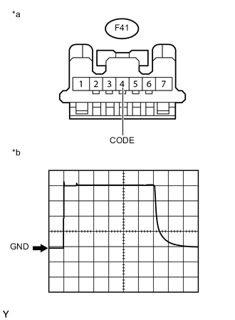
Text in Illustration *a Front view of wire harness connector
(to Transponder Key Amplifier)
*b Waveform Using an oscilloscope, check the waveform.
-
Waveform (Reference)
Measurement Condition Item Content Tester Connection F41-4 (CODE) - Body ground Tool Setting 1 V/DIV., 20 ms./DIV. Condition Key inserted in ignition key cylinder OK Waveform is output normally (refer to illustration).
-
OK
REPLACE TRANSPONDER KEY AMPLIFIER Click here
NG
-
-
CHECK HARNESS AND CONNECTOR (TRANSPONDER KEY AMPLIFIER - TRANSPONDER KEY ECU ASSEMBLY)
-
Disconnect the F41 transponder key amplifier connector.
-
Disconnect the F40 transponder key ECU assembly connector.
-
Measure the resistance according to the value(s) in the table below.
Standard Resistance Tester Connection Condition Specified Condition F41-4 (CODE) - F40-15 (CODE) Always Below 1 Ω F41-4 (CODE) - Body ground Always 10 kΩ or higher
OK
REPLACE TRANSPONDER KEY ECU ASSEMBLY
NG
REPAIR OR REPLACE HARNESS OR CONNECTOR
-