ENGINE IMMOBILISER SYSTEM(w/o Power Switch), Diagnostic DTC:B2799
| DTC Code | DTC Name |
|---|---|
| B2799 | Engine Immobiliser System Malfunction |
DESCRIPTION
This DTC is stored when one of the following occurs: 1) the power management control ECU detects errors in its own communications with the transponder key ECU assembly; 2) the power management control ECU detects errors in the communication lines; or 3) the ECU communication ID between the transponder key ECU assembly and power management control ECU is different and a hybrid control system start is attempted. Before troubleshooting for this DTC, make sure no engine immobiliser DTCs are output. If output, troubleshoot the engine immobiliser DTCs first.
| DTC Code | DTC Detection Condition | Trouble Area | DTC Output Confirmation Operation |
|---|---|---|---|
| B2799 | Either condition is met (1 trip detection logic*):
|
|
Either condition is met:
|
-
*: Only output while a malfunction is present.
| Vehicle Condition when Malfunction Detected | Fail-safe Operation when Malfunction Detected |
|---|---|
| Hybrid control system cannot be started | - |
| DTC Code | Data List and Active Test |
|---|---|
| B2799 | - |
WIRING DIAGRAM
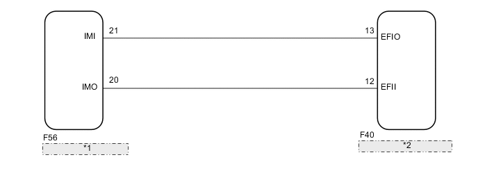
| *1 | Power Management Control ECU |
| *2 | Transponder Key ECU Assembly |
CAUTION / NOTICE / HINT
Note
-
When replacing the transponder key ECU assembly, refer to Service Bulletin.
-
After performing repairs, perform the operation that fulfills the DTC output confirmation operation, and then confirm that no DTCs are output again.
PROCEDURE
-
CLEAR DTC
-
Clear the DTCs Click here.
NEXT 
-
-
CHECK FOR DTC
-
Start the hybrid control system.
-
Wait 10 seconds or more.
-
Check for DTCs Click here.
Tech Tips
Before checking for DTCs, perform the "DTC Output Confirmation Operation" procedure.
OK DTC B2799 is not output. Result Result Proceed to OK A NG (DTC B2799 is output) B NG (Other DTCs are output) C
A 
USE SIMULATION METHOD TO CHECK Click here
C
GO TO DIAGNOSTIC TROUBLE CODE CHART Click here
B
-
-
INSPECT POWER MANAGEMENT CONTROL ECU (TERMINAL IMO)
-
Using an oscilloscope, check the waveform.
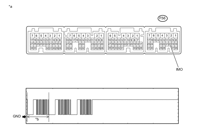
Text in Illustration *a Component with harness connected
(Power Management Control ECU)
*b Waveform Measurement Condition Item Content Tester Connection F56-20 (IMO) - Body ground Tool Setting 2 V/DIV., 500 ms./DIV. Condition Within 3 seconds after hybrid control system starts, or within 3 seconds after ignition switch first turned to ON after auxiliary battery disconnected and reconnected OK Waveform is output normally (refer to illustration). Result Result Proceed to Normal waveform A Terminal IMO stuck low (2.4 V or less) B Terminal IMO stuck high (12 V) or Abnormal waveform C
B 
INSPECT POWER MANAGEMENT CONTROL ECU (IMO TERMINAL VOLTAGE) Click here
C
REPLACE POWER MANAGEMENT CONTROL ECU Click here
A
-
-
INSPECT POWER MANAGEMENT CONTROL ECU (TERMINAL IMI)
-
Using an oscilloscope, check the waveform.
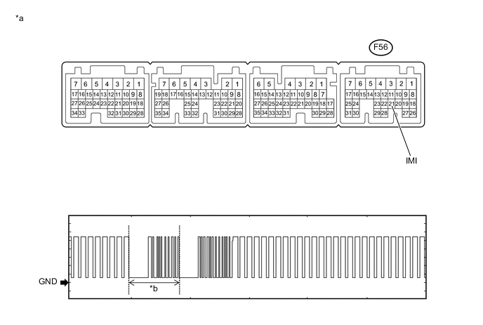
Text in Illustration *a Component with harness connected
(Power Management Control ECU)
*b Waveform Measurement Condition Item Content Tester Connection F56-21 (IMI) - Body ground Tool Setting 2 V/DIV., 500 ms./DIV. Condition Within 3 seconds after hybrid control system starts, or within 3 seconds after ignition switch first turned to ON after auxiliary battery disconnected and reconnected OK Waveform is output normally (refer to illustration). Result Result Proceed to Normal waveform A Not output waveform or abnormal waveform B
B
REPLACE TRANSPONDER KEY ECU ASSEMBLY Click here
A
-
-
REGISTER ECU COMMUNICATION ID
-
Reregister the ECU communication ID (Refer to Service Bulletin).
NEXT
-
-
CHECK WHETHER HYBRID CONTROL SYSTEM STARTS
-
Check that the hybrid control system starts with an already registered vehicle key.
OK Hybrid control system starts normally.
OK
END (COMMUNICATION ID REGISTRATION WAS DEFECTIVE)
NG
REPLACE POWER MANAGEMENT CONTROL ECU Click here
-
-
INSPECT POWER MANAGEMENT CONTROL ECU (IMO TERMINAL VOLTAGE)
-
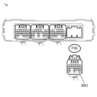
Text in Illustration *a Rear view of wire harness connector
(to Power Management Control ECU)
Disconnect the power management control ECU connector.
-
Turn the ignition switch to ON.
-
Measure the voltage according to the value(s) in the table below.
Result Result Proceed to Terminal IMO stuck low (2.4 V or less) A Terminal IMO stuck high (12 V) B
B
REPLACE POWER MANAGEMENT CONTROL ECU Click here
A
-
-
CHECK HARNESS AND CONNECTOR (TRANSPONDER KEY ECU - POWER MANAGEMENT CONTROL ECU AND BODY GROUND)
-
Disconnect the F40 transponder key ECU assembly connector.
-
Disconnect the F56 power management control ECU connector.
-
Measure the resistance according to the value(s) in the table below.
Standard Resistance Tester Connection Condition Specified Condition F40-12 (EFII) - F56-20 (IMO) Always Below 1 Ω F40-12 (EFII) - Body ground Always 10 kΩ or higher
NG
REPAIR OR REPLACE HARNESS OR CONNECTOR
OK
-
-
REPLACE TRANSPONDER KEY ECU ASSEMBLY
-
Replace the transponder key ECU assembly with a new one (Refer to Service Bulletin).
NEXT
-
-
REGISTER KEY
-
Reregister the key (Refer to Service Bulletin).
NEXT
-
-
REGISTER ECU COMMUNICATION ID
-
Reregister the ECU communication ID (Refer to Service Bulletin).
NEXT
-
-
CHECK WHETHER HYBRID CONTROL SYSTEM STARTS
-
Check that the hybrid control system starts with an already registered vehicle key.
OK Hybrid control system starts normally.
OK
END (TRANSPONDER KEY ECU ASSEMBLY WAS DEFECTIVE)
NG
REPLACE POWER MANAGEMENT CONTROL ECU Click here
-
-
REPLACE POWER MANAGEMENT CONTROL ECU
-
Temporarily replace the power management control ECU with a new one Click here.
NEXT
-
-
REGISTER ECU COMMUNICATION ID
-
Reregister the ECU communication ID (Refer to Service Bulletin).
NEXT
-
-
CHECK WHETHER HYBRID CONTROL SYSTEM STARTS
-
Check that the hybrid control system starts with an already registered vehicle key.
OK Hybrid control system starts normally.
OK
END (POWER MANAGEMENT CONTROL ECU WAS DEFECTIVE)
NG
REPLACE TRANSPONDER KEY ECU ASSEMBLY
-