ENGINE IMMOBILISER SYSTEM(w/o Power Switch) TERMINALS OF ECU
-
CHECK TRANSPONDER KEY AMPLIFIER

-
Measure the resistance and voltage according to the value(s) in the table below.
Terminal No. (Symbol) Input/Output Wiring Color Terminal Description Condition Specified Condition Related Data List Item/DTC F41-7 (AGND) - Body ground - GR - Body ground Ground Always Below 1 Ω - F41-1 (VC5) - F41-7 (AGND) Input P - GR Transponder key amplifier power supply No key in ignition key cylinder Below 1 V - F41-4 (CODE) - F41-7 (AGND) Output G - GR Demodulated signal of key code data No key in ignition key cylinder Below 1 V - F41-5 (TXCT) - F41-7 (AGND) Input L - GR Key code output signal No key in ignition key cylinder Below 1 V - -
Check for pulses according to the value(s) in the table below.
Terminal No. (Symbol) Input/Output Wiring Color Terminal Description Condition Specified Condition Related Data List Item/DTC F41-1 (VC5) - F41-7 (AGND) Input P - GR Transponder key amplifier power supply Key inserted in ignition key cylinder Pulse generation (See waveform 1)
-
BCC Malfunction
-
Abnormal Status
-
Different Encrypt Code
-
Different Serial Number
(If immobiliser key code certification communication is not performed correctly, a malfunction may be indicated by one or more of the Data List items listed above)
F41-4 (CODE) - F41-7 (AGND) Output G - GR Demodulated signal of key code data Key inserted in ignition key cylinder Pulse generation (See waveform 2) F41-5 (TXCT) - F41-7 (AGND) Input L - GR Key code output signal Key inserted in ignition key cylinder Pulse generation (See waveform 3) -
-
Inspect using an oscilloscope.
Note
The waveform shown in the illustration is an example for reference only. Noise, chattering, etc. are not shown.
-

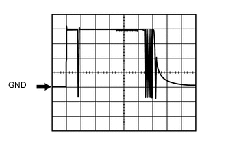
Waveform 1 (Reference)
Measurement Condition Item Content Tester Connection F41-1 (VC5) - F41-7 (AGND) Tool Setting 1 V/DIV., 20 ms./DIV. Condition Key inserted in ignition key cylinder -
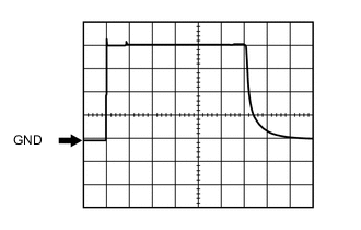
Waveform 2 (Reference)
Measurement Condition Item Content Tester Connection F41-4 (CODE) - F41-7 (AGND) Tool Setting 1 V/DIV., 20 ms./DIV. Condition Key inserted in ignition key cylinder -

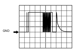
Waveform 3 (Reference)
Measurement Condition Item Content Tester Connection F41-5 (TXCT) - F41-7 (AGND) Tool Setting 1 V/DIV., 20 ms./DIV. Condition Key inserted in ignition key cylinder
-
-
-
CHECK TRANSPONDER KEY ECU ASSEMBLY
-
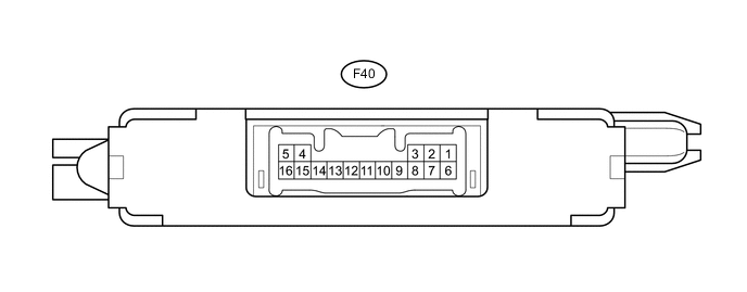
Disconnect the F40 transponder key ECU assembly connector.
-
Measure the resistance and voltage according to the value(s) in the table below.
Terminal No. (Symbol) Input/Output Wiring Color Terminal Description Condition Specified Condition Related Data List Item/DTC F40-16 (GND) - Body ground - BR - Body ground Ground Always Below 1 Ω - F40-1 (+B) - F40-16 (GND) Input Y - BR Auxiliary battery Ignition switch off 11 to 14 V +B F40-2 (IG) - F40-16 (GND) Input P - BR Ignition switch Ignition switch off Below 1 V IG SW Ignition switch ON 11 to 14 V F40-3 (KSW) - F40-16 (GND) Input BE - BR Unlock warning switch No key in ignition key cylinder 10 kΩ or higher Key SW/B2780 Key inserted in ignition key cylinder Below 1 Ω -
Reconnect the F40 transponder key ECU connector.
-
Measure the resistance and voltage, and check for pulses according to the value(s) in the table below.
Terminal No. (Symbol) Input/Output Wiring Color Terminal Description Condition Specified Condition Related Data List Item/DTC F40-14 (VC5) - F40-16 (GND) Input P - BR Transponder key amplifier power supply No key in ignition key cylinder Below 1 V
-
BCC Malfunction
-
Abnormal Status
-
Different Encrypt Code
-
Different Serial Number
(If immobiliser key code certification communication is not performed correctly, a malfunction may be indicated by one or more of the Data List items listed above)
Key inserted in ignition key cylinder Pulse generation (See waveform 1) F40-4 (TXCT) - F40-16 (GND) Input L - BR Key code output signal No key in ignition key cylinder Below 1 V Key inserted in ignition key cylinder Pulse generation (See waveform 2) F40-15 (CODE) - F40-16 (GND) Output G - BR Demodulated signal of key code data No key in ignition key cylinder Below 1 V Key inserted in ignition key cylinder Pulse generation (See waveform 3) F40-13 (EFIO) - F40-16 (GND) Input R - BR Power management control ECU output signal Ignition switch off Below 1 V E/G Start Permission Within 3 seconds after hybrid control system starts, or within 3 seconds after ignition switch first turned to ON after auxiliary battery disconnected and reconnected Pulse generation (See waveform 4) F40-12 (EFII) - F40-16 (GND) Output LG - BR Power management control ECU input signal Ignition switch off 11 to 14 V E/G Start Permission Within 3 seconds after hybrid control system starts, or within 3 seconds after ignition switch first turned to ON after auxiliary battery disconnected and reconnected Pulse generation (See waveform 5) F40-9 (D) - F40-16 (GND) Input/Output B - BR Diagnosis tester communication Always Pulse generation - F40-5 (AGND) - Body ground - GR - Body ground Transponder key amplifier ground Always Below 1 Ω - -
-
Inspect using an oscilloscope.
Note
The waveform shown in the illustration is an example for reference only. Noise, chattering, etc. are not shown.
-
Waveform 1 (Reference)
Measurement Condition Item Content Tester Connection F40-14 (VC5) - F40-16 (GND) Tool Setting 1 V/DIV., 20 ms./DIV. Condition Key inserted in ignition key cylinder -
Waveform 2 (Reference)
Measurement Condition Item Content Tester Connection F40-4 (TXCT) - F40-16 (GND) Tool Setting 1 V/DIV., 20 ms./DIV. Condition Key inserted in ignition key cylinder -

Waveform 3 (Reference)
Measurement Condition Item Content Tester Connection F40-15 (CODE) - F40-16 (GND) Tool Setting 1 V/DIV., 20 ms./DIV. Condition Key inserted in ignition key cylinder -
Waveform 4 (Reference)
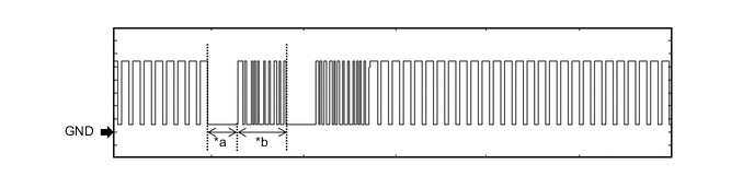
Text in Illustration *a Approximately 160 ms *b Approximately 270 ms Measurement Condition Item Content Tester Connection F40-13 (EFIO) - F40-16 (GND) Tool Setting 2 V/DIV., 500 ms./DIV. Condition Within 3 seconds after hybrid control system starts, or within 3 seconds after ignition switch first turned to ON after auxiliary battery disconnected and reconnected -
Waveform 5 (Reference)
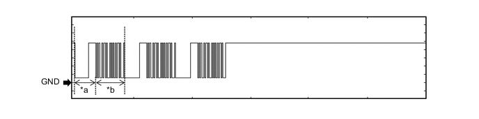
Text in Illustration *a Approximately 160 ms *b Approximately 270 ms Measurement Condition Item Content Tester Connection F40-12 (EFII) - F40-16 (GND) Tool Setting 2 V/DIV., 500 ms./DIV. Condition Within 3 seconds after hybrid control system starts, or within 3 seconds after ignition switch first turned to ON after auxiliary battery disconnected and reconnected
-
-
-
CHECK POWER MANAGEMENT CONTROL ECU
-
Measure the resistance and voltage, and check for pulses according to the value(s) in the table below.
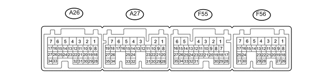
Terminal No. (Symbol) Input/Output Wiring Color Terminal Description Condition Specified Condition Related Data List Item/DTC A26-2 (+B2) - F55-5 (E01) Input L - W-B IG power supply Ignition switch ON 11 to 14 V - A27-5 (+B1) - F55-5 (E01) Input L - W-B IG power supply Ignition switch ON 11 to 14 V - A27-6 (MREL) - F55-5 (E01) Input BE - W-B IG power supply Ignition switch ON 11 to 14 V - F55-5 (E01) - Body ground - W-B - Body ground Ground Always Below 1 Ω - F55-6 (E1) - Body ground - BR - Body ground Ground Always Below 1 Ω - F56-5 (E02) - Body ground - W-B - Body ground Ground Always Below 1 Ω - F56-20 (IMO) - F55-6 (E1) Input LG - BR Transponder key ECU assembly communication input Ignition switch off 11 to 14 V E/G Start Permission Within 3 seconds after hybrid control system starts, or within 3 seconds after ignition switch first turned to ON after auxiliary battery disconnected and reconnected Pulse generation
(See waveform 1)
E/G Start Permission F56-21 (IMI) - F55-6 (E1) Output R - BR Transponder key ECU assembly communication output Ignition switch off Below 1 V E/G Start Permission Within 3 seconds after hybrid control system starts, or within 3 seconds after ignition switch first turned to ON after auxiliary battery disconnected and reconnected Pulse generation
(See waveform 2)
E/G Start Permission -
Inspect using an oscilloscope.
-
Waveform 1 (Reference)
Text in Illustration *a Approximately 160 ms *b Approximately 270 ms Measurement Condition Item Content Tester Connection F56-20 (IMO) - F55-6 (E1) Tool Setting 2 V/DIV., 500 ms./DIV. Condition Within 3 seconds after hybrid control system starts, or within 3 seconds after ignition switch first turned to ON after auxiliary battery disconnected and reconnected -
Waveform 2 (Reference)
Text in Illustration *a Approximately 160 ms *b Approximately 270 ms Measurement Condition Item Content Tester Connection F56-21 (IMI) - F55-6 (E1) Tool Setting 2 V/DIV., 500 ms./DIV. Condition Within 3 seconds after hybrid control system starts, or within 3 seconds after ignition switch first turned to ON after auxiliary battery disconnected and reconnected
-
-