ENTRY AND START SYSTEM(for Start Function), Diagnostic DTC:B2271
| DTC Code | DTC Name |
|---|---|
| B2271 | Ignition Hold Monitor Malfunction |
DESCRIPTION
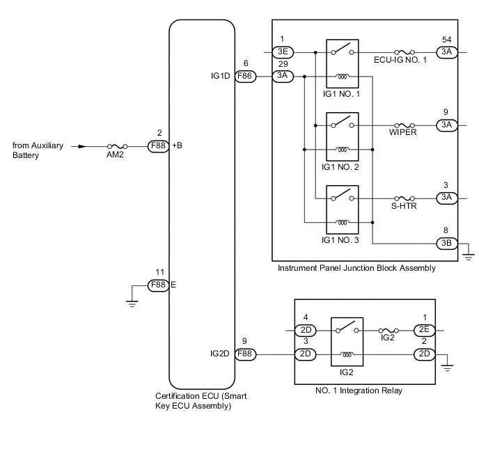
This DTC is stored when a malfunction in the IG1 circuit, IG2 circuit or IG hold circuit in the certification ECU (smart key ECU assembly) is detected.
Tech Tips
When the cable is disconnected and reconnected to the negative (-) auxiliary battery terminal, the power source mode returns to the state it was in before the cable was disconnected.
| DTC Code | DTC Detection Condition | Trouble Area | DTC Output Confirmation Operation |
|---|---|---|---|
| B2271 | When either of the following conditions is met (1-trip detection logic*):
|
|
Turn the power switch on (IG). Tech Tips To turn the power switch on (IG), carry the electrical key transmitter sub-assembly and press the power switch twice with the shift lever in P and the brake pedal released. |
-
*: Only detected while a malfunction is present and the power switch is on (IG)
Tech Tips
-
The IG1 and IG2 circuits activate the IG1 and IG2 relays.
-
After the IG1 and IG2 circuits turn on, even if the CPU operates incorrectly, the IG hold circuit maintains the power source mode in on (IG).
| Vehicle Condition when Malfunction Detected | Fail-safe Function when Malfunction Detected |
|---|---|
| The power switch cannot be turned on (IG) (the hybrid control system cannot be started). | The power source mode cannot be changed to on (IG). |
| DTC | Data List Item | Active Test Item |
|---|---|---|
| B2271 |
Power Source Control |
- |
WIRING DIAGRAM
CAUTION / NOTICE / HINT
Note
-
When using the GTS with the vehicle power switch off, connect the GTS to the vehicle and turn a courtesy light switch on and off at intervals of 1.5 seconds or less until communication between the GTS and the vehicle begins. Then select the Model Code "KEY REGIST" under manual mode and enter the following menus: Body Electrical / Entry & Start(CAN). While using the GTS, periodically turn a courtesy light switch on and off at intervals of 1.5 seconds or less to maintain communication between the GTS and the vehicle.
-
The entry and start system uses multiplex communication. First perform the inspections in "How to Proceed with Troubleshooting" to confirm that there are no communication malfunctions before proceeding with troubleshooting Click here.
-
Before replacing the certification ECU (smart key ECU assembly), refer to the entry and start system (for Entry Function) precaution Click here.
-
After performing repairs, perform the operation that fulfills the DTC output confirmation operation, and then confirm that no DTCs are output again.
-
Inspect the fuses of circuits related to this system before performing the following inspection procedure.
PROCEDURE
-
CHECK HARNESS AND CONNECTOR (POWER SOURCE)
-
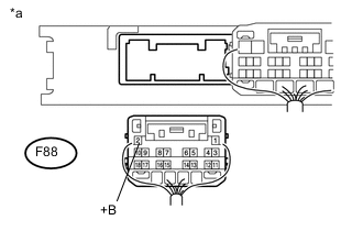
Text in Illustration *a Rear view of wire harness connector
(to Certification ECU (Smart Key ECU Assembly))
Disconnect the certification ECU (smart key ECU assembly) connector.
-
Measure the voltage according to the value(s) in the table below.
Standard Voltage Tester Connection Switch Condition Specified Condition F88-2 (+B) - Body ground Power switch off 11 to 14 V
NG 
REPAIR OR REPLACE HARNESS OR CONNECTOR IN CIRCUIT CONNECTED TO POWER SOURCE
OK 
-
-
CHECK HARNESS AND CONNECTOR (GROUND)
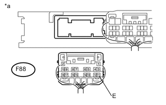
Text in Illustration *a Rear view of wire harness connector
(to Certification ECU (Smart Key ECU Assembly))
-
Measure the resistance according to the value(s) in the table below.
Standard Resistance Tester Connection Condition Specified Condition F88-11 (E) - Body ground Always Below 1 Ω
NG
REPAIR OR REPLACE HARNESS OR CONNECTOR
OK
-
-
CHECK CERTIFICATION ECU (SMART KEY ECU ASSEMBLY)
-
Reconnect the certification ECU (smart key ECU assembly) connector.
-
Measure the voltage according to the value(s) in the table below.
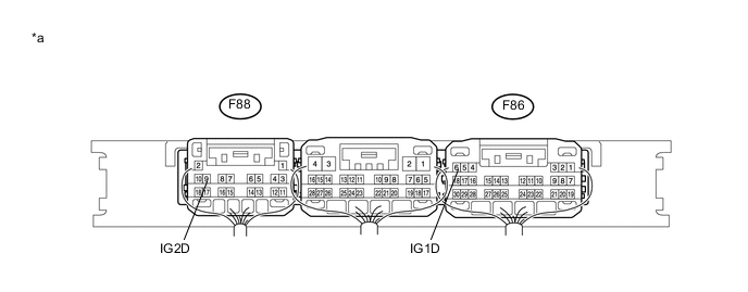
Standard Voltage Tester Connection Switch Condition Specified Condition F88-9 (IG2D) - Body ground Power switch on (ACC) → Power switch on (IG) 1 V or less → 9 V or higher F86-6 (IG1D) - Body ground Power switch on (ACC) → Power switch on (IG) 1 V or less → 9 V or higher Text in Illustration *a Component with harness connected
(to Certification ECU (Smart Key ECU Assembly))
OK
END (USE SIMULATION METHOD TO CHECK) Click here
NG
REPLACE CERTIFICATION ECU (SMART KEY ECU ASSEMBLY)
-