ENTRY AND START SYSTEM(for Entry Function) Back Door Entry Unlock Function does not Operate
DESCRIPTION
If the back door entry unlock function does not operate but the back door lock function operates, the communication between the vehicle and electrical key transmitter sub-assembly is normal. The malfunctioning part may be the entry unlock switch circuit (certification ECU (smart key ECU assembly) and back door opener switch assembly (unlock switch)).
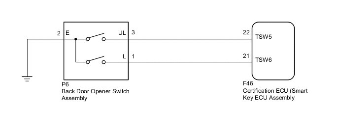
WIRING DIAGRAM
CAUTION / NOTICE / HINT
Note
-
When using the GTS with the vehicle power switch off, connect the GTS to the vehicle and turn a courtesy light switch on and off at intervals of 1.5 seconds or less until communication between the GTS and the vehicle begins. Then select the Model Code "KEY REGIST" under manual mode and enter the following menus: Body Electrical / Entry & Start(CAN). While using the GTS, periodically turn a courtesy light switch on and off at intervals of 1.5 seconds or less to maintain communication between the GTS and the vehicle.
-
The entry and start system (for Entry Function) uses a LIN communication system and CAN communication system. Inspect the communication function by following How to Proceed with Troubleshooting Click here. Troubleshoot the entry and start system (for Entry Function) after confirming that the communication system is functioning properly.
-
Before replacing the certification ECU, refer to the entry and start system (for Entry Function) precaution Click here.
-
When checking the entry lock operation multiple times, the lock operation may be limited to 2 consecutive operations depending on the settings. In order to perform the entry lock operation 3 or more times, an unlock operation must be performed once (any type of unlock operation is sufficient). However, only consecutive entry lock operations are limited. Using the wireless lock or other types of lock operations, it is possible to perform consecutive lock operations without this limitation.
PROCEDURE
-
CHECK POWER DOOR LOCK CONTROL SYSTEM
-
When the door control switch on the master switch assembly is operated, check that the doors lock according to switch operation Click here.
OK Door locks operate normally.
NG 
GO TO POWER DOOR LOCK CONTROL SYSTEM (PROCEED TO PROBLEM SYMPTOMS TABLE) Click here
OK 
-
-
READ VALUE USING GTS (B-DR OPENING OPERATION)
-
Connect the GTS to the DLC3.
-
Turn the power switch on (IG).
-
Turn the GTS on.
-
Enter the following menus: Body Electrical / Entry & Start / Data List.
-
According to the display on the GTS, read the Data List.
Entry & Start Tester Display Measurement Item/Range Normal Condition Diagnostic Note B-Dr Opening Operation Back door opening operation / Long, Twice, OFF Customization status displayed - Result Result Proceed to Back door opening operation is Long or Twice A Back door opening operation is OFF B
B
PERFORM CUSTOMIZE SETTING (PROCEED TO CUSTOMIZE PARAMETERS) Click here
A
-
-
READ VALUE USING GTS (TR/B-DOOR UNLOCK SW)
-
Connect the GTS to the DLC3.
-
Turn the power switch on (IG).
-
Turn the GTS on.
-
Enter the following menus: Body Electrical / Entry & Start / Data List.
-
According to the display on the GTS, read the Data List.
Entry & Start Tester Display Measurement Item/Range Normal Condition Diagnostic Note Tr/B-Door Unlock SW Back door opener switch assembly (unlock switch) / OFF or ON OFF: Back door opener switch assembly (unlock switch) not pushed
ON: Back door opener switch assembly (unlock switch) pushed
-
Displays whether the back door electrical key switch (unlock switch) is on or off.
-
Use this Data List item to help determine if there is a switch malfunction when the back door unlock function does not operate.
OK On the GTS screen, the display changes between ON and OFF as shown in the table above. -
OK
REPLACE CERTIFICATION ECU (SMART KEY ECU ASSEMBLY)
NG
-
-
CHECK HARNESS AND CONNECTOR (BACK DOOR OPENER SWITCH ASSEMBLY - CERTIFICATION ECU (SMART KEY ECU ASSEMBLY) AND BODY GROUND
-
Disconnect the F46 certification ECU (smart key ECU assembly) connector.
-
Disconnect the P6 back door opener switch assembly connector.
-
Measure the resistance according to the value(s) in the table below.
Standard Resistance Tester Connection Condition Specified Condition F46-22 (TSW5) - P6-3 (UL) Always Below 1 Ω P6-2 (E) - Body ground Always Below 1 Ω F46-22 (TSW5) - Body ground Always 10 kΩ or higher
NG
REPAIR OR REPLACE HARNESS OR CONNECTOR
OK
-
-
INSPECT BACK DOOR OPENER SWITCH ASSEMBLY
-
Inspect the back door opener switch assembly Click here.
OK
REPLACE CERTIFICATION ECU (SMART KEY ECU ASSEMBLY)
NG
REPLACE BACK DOOR OPENER SWITCH ASSEMBLY Click here
-