KEY REMINDER WARNING SYSTEM(w/o Power Switch) TERMINALS OF ECU
-
CHECK MAIN BODY ECU AND INSTRUMENT PANEL JUNCTION BLOCK ASSEMBLY
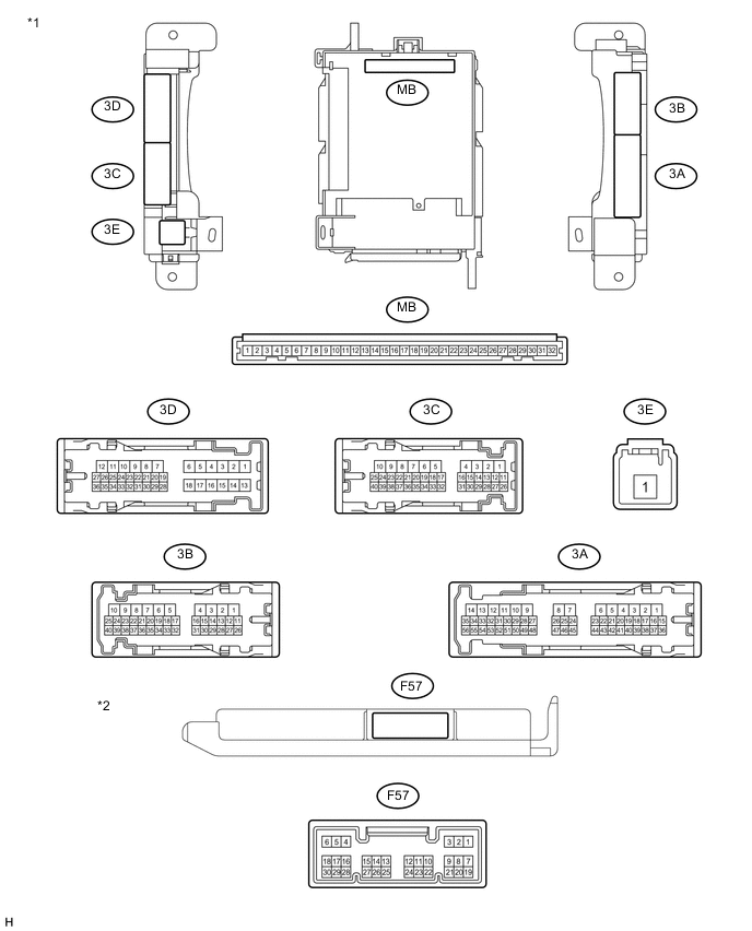
Text in Illustration *1 Instrument Panel Junction Block Assembly *2 Main Body ECU
-
Remove the main body ECU from the instrument panel junction block assembly.
-
Disconnect the F57 main body ECU connector.
-
Measure the voltage and resistance according to the value(s) in the table below.
Terminal No. (Symbol) Wiring Color Terminal Description Condition Specified Condition MB-11 (GND1) - Body ground None - Body ground Ground Always Below 1 Ω MB-30 (BECU) - Body ground None - Body ground Auxiliary Battery power supply Always 11 to 14 V MB-29 (ACC) - Body ground None - Body ground ACC power supply Ignition switch ACC 11 to 14 V MB-32 (IG) - Body ground None - Body ground IG power supply Ignition switch ON (IG) 11 to 14 V F57-17 (KSW) - Body ground Y - Body ground Unlock warning switch input No Key in ignition key cylinder (off) 10 kΩ or higher Key inserted ignition key cylinder (on) Below 1 Ω -
Install the main body ECU to the instrument panel junction block assembly.
-
Reconnect the F57 main body ECU connector.
-
Measure the voltage and check for pulse according to the value(s) in the table below.
Terminal No. (Symbol) Wiring Color Terminal Description Condition Specified Condition 3D-36 (FLCY) - Body ground L - Body ground Front door LH courtesy light switch input Front door LH open Below 1 V Front door LH closed Pulse generation F57-19 (FRCY) - Body ground Y - Body ground Front door RH courtesy light switch input Front door RH open Below 1 V Front door RH closed Pulse generation F57-17 (KSW) - Body ground Y - Body ground Unlock warning switch input No Key in ignition key cylinder (off) 11 to 14 V Key inserted ignition key cylinder (on) Below 1 V
-