CAN COMMUNICATION SYSTEM(w/o Toyota Safety Sense) SYSTEM DIAGRAM
-
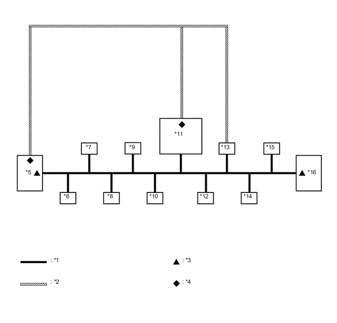
OVERALL CAN BUS DIAGRAM (for LHD)
-
Control system CAN is composed of 2 buses.

Text in Illustration *1 V Bus *2 Sub Bus 15 *3 V Bus Terminating Resistor *4 Sub Bus 15 Terminating Resistor *5 ECM
(for V Bus and Sub Bus 15)
*6 Main Body ECU (Multiplex Network Body ECU)
(for V Bus)
*7 Airbag Sensor Assembly
(for V Bus)
*8 Spiral Cable with Sensor Sub-assembly (Steering Sensor)
(for V Bus)
*9 Power Steering ECU Assembly
(for V Bus)
*10 Air Conditioning Amplifier Assembly
(for V Bus)
*11 Power Management Control ECU
(for V Bus and Sub Bus 15)
*12 Smart Key ECU Assembly (Certification ECU)*1
(for V Bus)
*13 Brake Booster with Master Cylinder Assembly (Skid Control ECU)
(for V Bus and Sub Bus 15)
*14 DLC3
(for V Bus)
*15 Radio and Display Receiver Assembly*2
(for V Bus)
*16 Combination Meter Assembly
(for V Bus)
-
*1: w/ Entry and Start System
-
*2: w/ Display
-
Tech Tips
Refer to the following bus wiring diagrams for details.
-
-
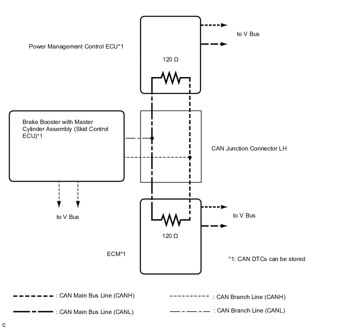
V BUS (for LHD)
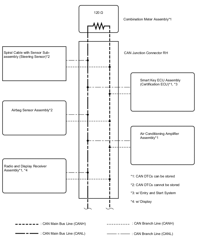
Tech Tips
The CAN communication system connects to other network via ECUs that function as a gateway Click here.
-
OVERALL CAN BUS DIAGRAM (for RHD)
-
Control system CAN is composed of 2 buses.
Text in Illustration *1 V Bus *2 Sub Bus 15 *3 V Bus Terminating Resistor *4 Sub Bus 15 Terminating Resistor *5 ECM
(for V Bus and Sub Bus 15)
*6 Main Body ECU (Multiplex Network Body ECU)
(for V Bus)
*7 Airbag Sensor Assembly
(for V Bus)
*8 Spiral Cable with Sensor Sub-assembly (Steering Sensor)
(for V Bus)
*9 Power Steering ECU Assembly
(for V Bus)
*10 Air Conditioning Amplifier Assembly
(for V Bus)
*11 Power Management Control ECU
(for V Bus and Sub Bus 15)
*12 Smart Key ECU Assembly (Certification ECU)*1
(for V Bus)
*13 Brake Booster with Master Cylinder Assembly (Skid Control ECU)
(for V Bus and Sub Bus 15)
*14 DLC3
(for V Bus)
*15 Radio and Display Receiver Assembly*2
(for V Bus)
*16 Combination Meter Assembly
(for V Bus)
-
*1: w/ Entry and Start System
-
*2: w/ Display
Tech Tips
Refer to the following bus wiring diagrams for details.
-
-
-
V BUS (for RHD)
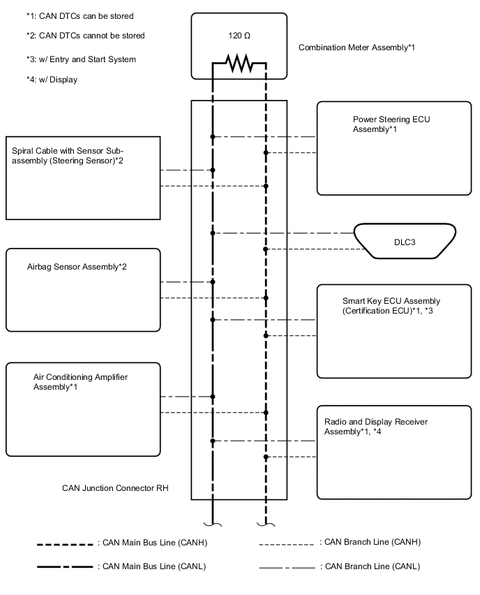
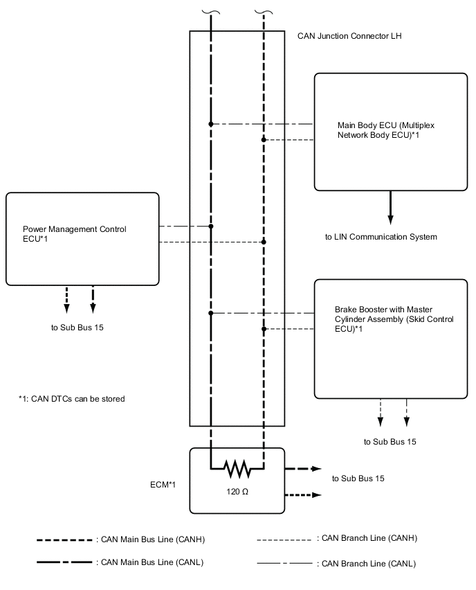
Tech Tips
The CAN communication system connects to other network via ECUs that function as a gateway Click here.
-
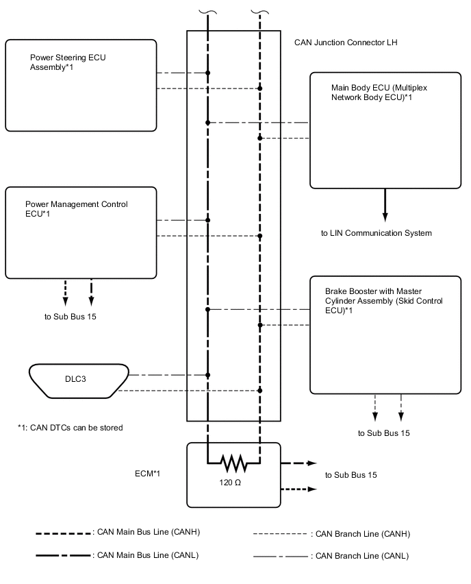
SUB BUS 15