CAN COMMUNICATION SYSTEM(w/ Toyota Safety Sense) TERMINALS OF ECU
Note
-
After turning the ignition switch off, waiting time may be required before disconnecting the cable from the negative (-) auxiliary battery terminal. Therefore, make sure to read the disconnecting the cable from the negative (-) auxiliary battery terminal notices before proceeding with work Click here.
-
Turn the ignition switch off before measuring the resistances between CAN main bus lines and between CAN branch lines.
-
Turn the ignition switch off before inspecting CAN bus lines for a ground short.
-
Before measuring the resistance of the CAN bus, turn the ignition switch off and leave the vehicle for 1 minute or more without operating the key, switches or opening or closing the doors. After that, disconnect the cable from the negative (-) auxiliary battery terminal and leave the vehicle for 1 minute or more before measuring the resistance.
-
This section describes the standard values for all CAN related components.
Tech Tips
-
Operating the ignition switch, any other switches or a door triggers related ECU and sensor communication on the CAN. This communication will cause the resistance value to change.
-
Even after DTCs are cleared, if a DTC is stored again after driving the vehicle for a while, the malfunction may be occurring due to vibration of the vehicle. In such a case, wiggling the ECUs or wire harness while performing the inspection below may help determine the cause of the malfunction.
-
CAN JUNCTION CONNECTOR LH
Tech Tips
The following tables contain information about the items and buses connected via junction connectors. The junction connector may be used for multiple separate buses. In this case, the name of the bus will be shown below the name of the item that the terminals are connected to. The bus name will be shown in brackets (example: (for Sub bus 15)).
-
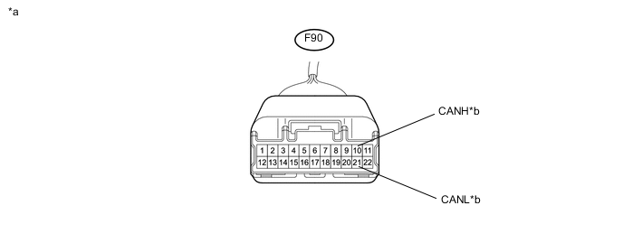
Check the CAN junction connector LH (instrument panel wire side) (for bus 2).
-
Connection diagram
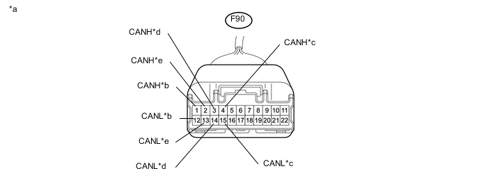
Text in Illustration *a Front view of wire harness connector
(to CAN Junction Connector LH (Instrument Panel Wire Side))
*b to Main Body ECU (Multiplex Network Body ECU)
(for Bus 2)
*c to CAN Junction Connector RH
(for Bus 2)
*d to Hybrid Vehicle Control ECU
(for Bus 2)
*e Pre-crash Safety City Sensor
(for Bus 2)
- - -
Check the connection diagram of the components which are connected to the CAN junction connector LH.
Terminal No. (Symbol) Wiring Color Connected to F90-1 (CANH) R Main body ECU (Multiplex network body ECU)
(for bus 2)
F90-12 (CANL) W F90-2 (CANH) R Pre-crash Safety City Sensor
(for bus 2)
F90-13 (CANL) W F90-3 (CANH) BE Hybrid vehicle control ECU
(for bus 2)
F90-14 (CANL) W F90-4 (CANH) SB CAN junction connector RH
(for bus 2)
F90-15 (CANL) W
-
-
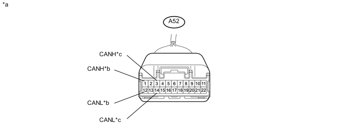
Check the CAN junction connector LH (engine room main wire side) (for bus 2).
-
Connection diagram
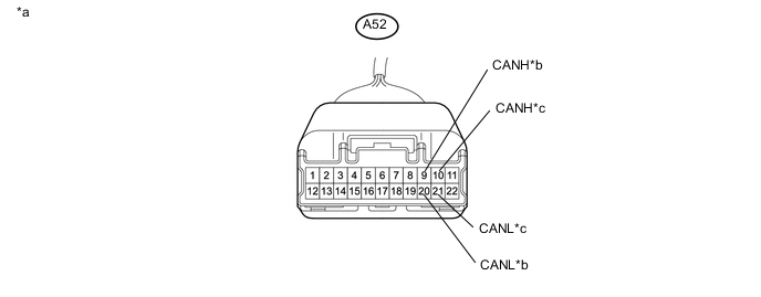
Text in Illustration *a Front view of wire harness connector
(to CAN Junction Connector LH (Engine Room Main Wire Side))
*b to ECM
(for Bus 2)
*c to Brake Booster with Master Cylinder Assembly (Skid Control ECU)
(for Bus 2)
- - -
Check the connection diagram of the components which are connected to the CAN junction connector LH.
Terminal No. (Symbol) Wiring Color Connected to A52-9 (CANH) L ECM
(for bus 2)
A52-20 (CANL) W A52-10 (CANH) B Brake booster with master cylinder assembly (Skid control ECU)
(for bus 2)
A52-21 (CANL) W
-
-
-
CAN JUNCTION CONNECTOR RH
-
Check the CAN junction connector RH (for bus 2).
-
Connection diagram
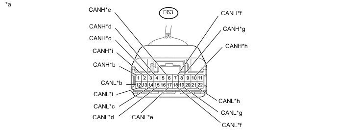
Text in Illustration *a Front view of wire harness connector
(to CAN Junction Connector RH)
*b to Spiral Cable with Sensor Sub-assembly (Steering Sensor)
(for Bus 2)
*c to Smart Key ECU Assembly (Certification ECU)*1
(for Bus 2)
*d to Airbag Sensor Assembly
(for Bus 2)
*e to Power Steering ECU Assembly
(for Bus 2)
*f to Combination Meter Assembly
(for Bus 2)
*g to Air Conditioning Amplifier Assembly
(for Bus 2)
*h to CAN Junction Connector LH
(for Bus 2)
*i to Central Gateway ECU (Network Gateway ECU)
(for Bus 2)
- -
-
*1: w/ Power Switch
-
-
Check the connection diagram of the components which are connected to the CAN junction connector RH.
Terminal No. (Symbol) Wiring Color Connected to F63-1 (CANH) P Spiral cable with sensor sub-assembly (Steering sensor)
(for bus 2)
F63-12 (CANL) W F63-2 (CANH) L Central gateway ECU (network gateway ECU)
(for bus 2)
F63-13 (CANL) W F63-3 (CANH) L Smart key ECU assembly (Certification ECU)*1
(for bus 2)
F63-14 (CANL) W F63-4 (CANH) B Airbag sensor assembly
(for bus 2)
F63-15 (CANL) W F63-6 (CANH) LG Power Steering ECU Assembly
(for bus 2)
F63-17 (CANL) W F63-7 (CANH) G Combination meter assembly
(for bus 2)
F63-18 (CANL) W F63-8 (CANH) V Air conditioning amplifier assembly
(for bus 2)
F63-19 (CANL) W F63-10 (CANH) SB CAN junction connector LH
(for bus 2)
F63-21 (CANL) W
-
*1: w/ Power Switch
-
-
-
-
CAN JUNCTION CONNECTOR LH
-
Check the CAN junction connector LH (instrument panel wire side) (for bus 3).
-
Connection diagram
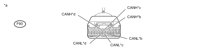
Text in Illustration *a Front view of wire harness connector
(to CAN Junction Connector LH (Instrument Panel Wire Side))
*b to Central Gateway ECU (Network Gateway ECU) (CA3H and CA3L Terminal)
(for Bus 3)
*c to Central Gateway ECU (Network Gateway ECU) (CAYH and CAYL Terminal)
(for Bus 3)
*d to Radio and Display Receiver Assembly*1
(for Bus 3)
-
*1: w/ Display
-
-
Check the connection diagram of the components which are connected to the CAN junction connector LH.
Terminal No. (Symbol) Wiring Color Connected to F90-5 (CANH) BE Radio and display receiver assembly*1
(for Bus 3)
F90-16 (CANL) W F90-6 (CANH) R Central gateway ECU (network gateway ECU) (CAYH and CAYL terminal)
(for Bus 3)
F90-17 (CANL) W F90-7 (CANH) G Central gateway ECU (network gateway ECU) (CA3H and CA3L terminal)
(for Bus 3)
F90-18 (CANL) W
-
*1: w/ Display
-
-
-
-
CAN JUNCTION CONNECTOR LH
-
Check the CAN junction connector LH (engine room main wire side) (for Sub bus 15).
-
Connection diagram
Text in Illustration *a Front view of wire harness connector
(to CAN Junction Connector LH (Engine Room Main Wire Side))
*b to Brake Booster with Master Cylinder Assembly (Skid Control ECU)
(for Sub Bus 15)
*c to ECM
(for Sub Bus 15)
- - -
Check the connection diagram of the components which are connected to the CAN junction connector LH.
Terminal No. (Symbol) Wiring Color Connected to A52-1 (CANH) L Brake booster with master cylinder assembly (Skid control ECU)
(for Sub bus 15)
A52-12 (CANL) W A52-3 (CANH) B*1, G*2 ECM
(for Sub bus 15)
A52-14 (CANL) W
-
*1: for LHD
-
*2: for RHD
-
-
-
Check the CAN junction connector LH (instrument panel wire side) (for Sub bus 15).
-
Connection diagram
Text in Illustration *a Front view of wire harness connector
(to CAN Junction Connector LH (Instrument Panel Wire Side))
*b to Hybrid Vehicle Control ECU
(for Sub Bus 15)
-
Check the connection diagram of the components which are connected to the CAN junction connector LH.
Terminal No. (Symbol) Wiring Color Connected to F90-10 (CANH) Y Hybrid vehicle control ECU
(for Sub bus 15)
F90-21 (CANL) W
-
-
-
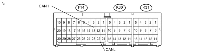
DLC3
-
Disconnect the cable from the negative (-) auxiliary battery terminal.
-
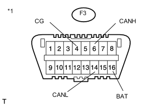
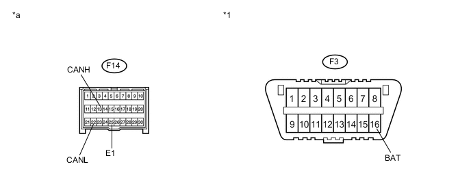
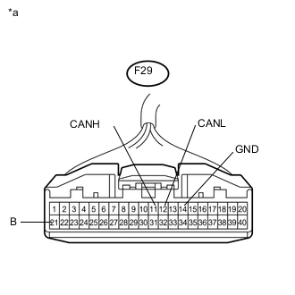
Text in Illustration *1 DLC3 Measure the resistance according to the value(s) in the table below.
-
-
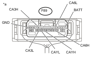
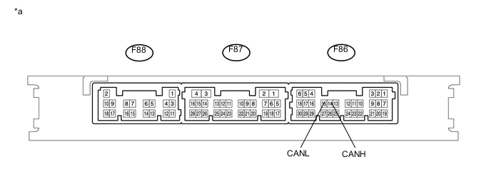
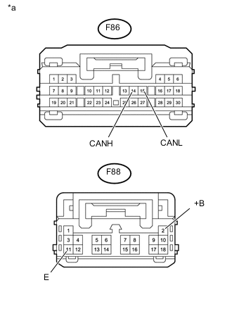
CENTRAL GATEWAY ECU (NETWORK GATEWAY ECU)

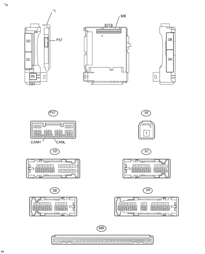
Text in Illustration *a Component without harness connected
(Central Gateway ECU (Network Gateway ECU))
- -
-
Disconnect the cable from the negative (-) auxiliary battery terminal.
-
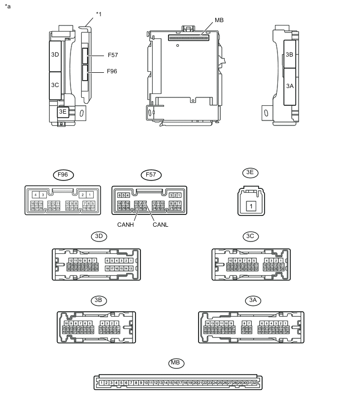
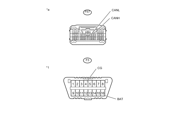
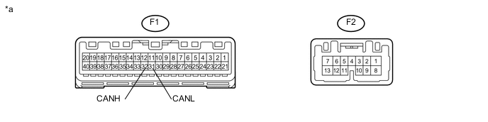
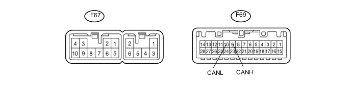
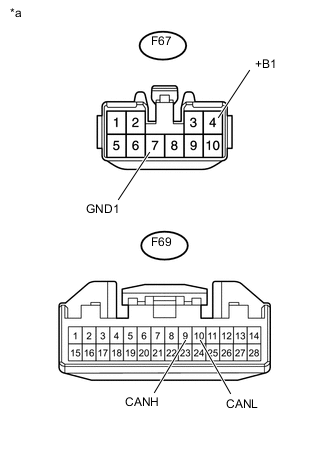
Text in Illustration *a Front view of wire harness connector
(to Central Gateway ECU (Network Gateway ECU))
Disconnect the central gateway ECU (network gateway ECU) connector.
-
Measure the resistance according to the value(s) in the table below.
-
Text in Illustration *a Rear view of wire harness connector
(to Central Gateway ECU (Network Gateway ECU))
Reconnect the central gateway ECU (network gateway ECU) connector.
-
Measure the resistance according to the value(s) in the table below.
-
-
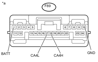
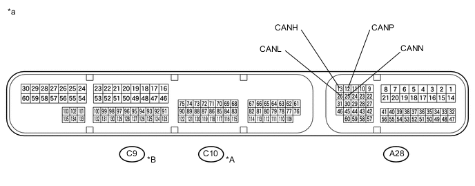
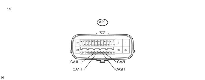
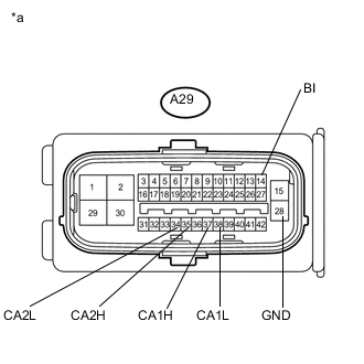
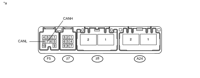
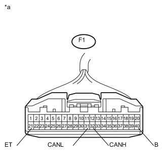
HYBRID VEHICLE CONTROL ECU
Text in Illustration *a Component without harness connected
(Hybrid Vehicle Control ECU)
- -
-
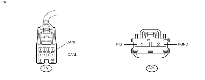
Disconnect the cable from the negative (-) auxiliary battery terminal.
-
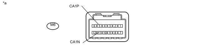
Text in Illustration *a Rear view of wire harness connector
(to Hybrid Vehicle Control ECU)
Disconnect the hybrid vehicle control ECU connectors.
-
Measure the resistance according to the value(s) in the table below.
-
-
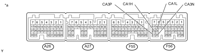
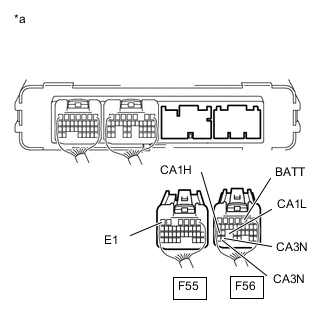
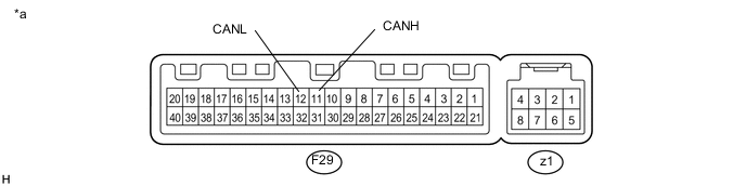
ECM
Text in Illustration *A for LHD *B for RHD *a Component without harness connected
(ECM)
- -
-
Disconnect the cable from the negative (-) auxiliary battery terminal.
-
Disconnect the ECM connectors.
Text in Illustration *A for LHD *B for RHD *a Front view of wire harness connector
(to ECM)
- - -
Measure the resistance according to the value(s) in the table below.
-
*1: for LHD
-
*2: for RHD
-
*1: for LHD
-
*2: for RHD
-
-
-
BRAKE BOOSTER WITH MASTER CYLINDER ASSEMBLY (SKID CONTROL ECU)
Text in Illustration *a Component without harness connected
(Brake Booster with Master Cylinder Assembly (Skid Control ECU))
- -
-
Disconnect the cable from the negative (-) auxiliary battery terminal.
-
Text in Illustration *a Front view of wire harness connector
(to Brake Booster with Master Cylinder Assembly (Skid Control ECU))
Disconnect the brake booster with master cylinder assembly (skid control ECU) connector.
-
Measure the resistance according to the value(s) in the table below.
-
-
AIRBAG SENSOR ASSEMBLY
Text in Illustration *a Component without harness connected
(Airbag Sensor Assembly)
- -
-
Disconnect the cable from the negative (-) auxiliary battery terminal.
-
Disconnect the airbag sensor assembly connector.
Text in Illustration *1 DLC3 - - *a Front view of wire harness connector
(to Airbag Sensor Assembly)
- - -
Measure the resistance according to the value(s) in the table below.
-
-
MAIN BODY ECU (MULTIPLEX NETWORK BODY ECU) (2 Connector Type)
Text in Illustration *1 Main Body ECU (Multiplex Network Body ECU) - - *a Component without harness connected
(Main body ECU (Multiplex Network Body ECU))
- -
-
Disconnect the cable from the negative (-) auxiliary battery terminal.
-
Disconnect the main body ECU (multiplex network body ECU) connector.
Text in Illustration *1 DLC3 - - *a Front view of wire harness connector
(to Main Body ECU (Multiplex Network Body ECU))
- - -
Measure the resistance according to the value(s) in the table below.
-
-
MAIN BODY ECU (MULTIPLEX NETWORK BODY ECU) (1 Connector Type)
Text in Illustration *1 Main Body ECU (Multiplex Network Body ECU) - - *a Component without harness connected
(Main body ECU (Multiplex Network Body ECU))
- -
-
Disconnect the cable from the negative (-) auxiliary battery terminal.
-
Disconnect the main body ECU (multiplex network body ECU) connector.

Text in Illustration *1 DLC3 - - *a Front view of wire harness connector
(to Main Body ECU (Multiplex Network Body ECU))
- - -
Measure the resistance according to the value(s) in the table below.
-
-
SPIRAL CABLE WITH SENSOR SUB-ASSEMBLY (STEERING SENSOR)
-
Disconnect the cable from the negative (-) auxiliary battery terminal.
-
Text in Illustration *a Front view of wire harness connector
(to Spiral Cable with Sensor Sub-assembly (Steering Sensor))
Disconnect the spiral cable with sensor sub-assembly (steering sensor) connector.
-
Measure the resistance according to the value(s) in the table below.
-
-
POWER STEERING ECU ASSEMBLY
Text in Illustration *a Component without harness connected
(Power Steering ECU Assembly)
- -
-
Disconnect the cable from the negative (-) auxiliary battery terminal.
-
Disconnect the power steering ECU assembly connectors.
Text in Illustration *a Front view of wire harness connector
(to Power Steering ECU Assembly)
- - -
Measure the resistance according to the value(s) in the table below.
-
-
SMART KEY ECU ASSEMBLY (CERTIFICATION ECU) (w/ Power Switch)
Text in Illustration *a Component without harness connected
(Smart Key ECU Assembly (Certification ECU))
- -
-
Disconnect the cable from the negative (-) auxiliary battery terminal.
-
Text in Illustration *a Front view of wire harness connector
(to Smart Key ECU Assembly (Certification ECU))
Disconnect the smart key ECU assembly (certification ECU) connectors.
-
Measure the resistance according to the value(s) in the table below.
-
-
COMBINATION METER ASSEMBLY
Text in Illustration *a Component without harness connected
(Combination Meter Assembly)
- -
-
Disconnect the cable from the negative (-) auxiliary battery terminal.
-
Text in Illustration *a Front view of wire harness connector
(to Combination Meter Assembly)
Disconnect the combination meter assembly connector.
-
Measure the resistance according to the value(s) in the table below.
-
-
AIR CONDITIONING AMPLIFIER ASSEMBLY
Text in Illustration *a Component without harness connected
(Air Conditioning Amplifier Assembly)
- -
-
Disconnect the cable from the negative (-) auxiliary battery terminal.
-
Text in Illustration *a Front view of wire harness connector
(to Air Conditioning Amplifier Assembly)
Disconnect the air conditioning amplifier assembly connector.
-
Measure the resistance according to the value(s) in the table below.
-
-
RADIO AND DISPLAY RECEIVER ASSEMBLY (w/ Display)
Text in Illustration *a Component without harness connected
(Radio and Display Receiver Assembly)
- -
-
Disconnect the cable from the negative (-) auxiliary battery terminal.
-
Text in Illustration *a Front view of wire harness connector
(to Radio and Display Receiver Assembly)
Disconnect the radio and display receiver assembly connectors.
-
Measure the resistance according to the value(s) in the table below.
-
-
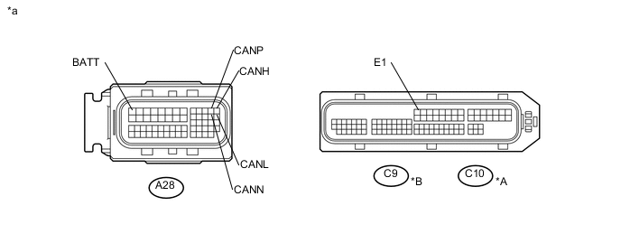
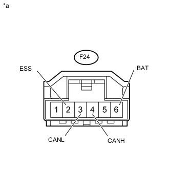
PRE-CRASH SAFETY CITY SENSOR
Text in Illustration *a Component without harness connected
(Pre-crash Safety City Sensor)
- -
-
Disconnect the cable from the negative (-) auxiliary battery terminal.
-
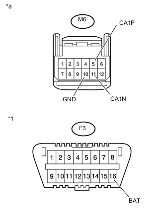
Text in Illustration *1 DLC3 *a Front view of wire harness connector
(to Pre-crash Safety City Sensor)
Disconnect the pre-crash safety city sensor connector.
-
Measure the resistance according to the value(s) in the table below.
-