CAN COMMUNICATION SYSTEM(w/ Toyota Safety Sense) SYSTEM DIAGRAM
-
OVERALL CAN BUS DIAGRAM
-
The CAN communication system is composed of 4 buses.
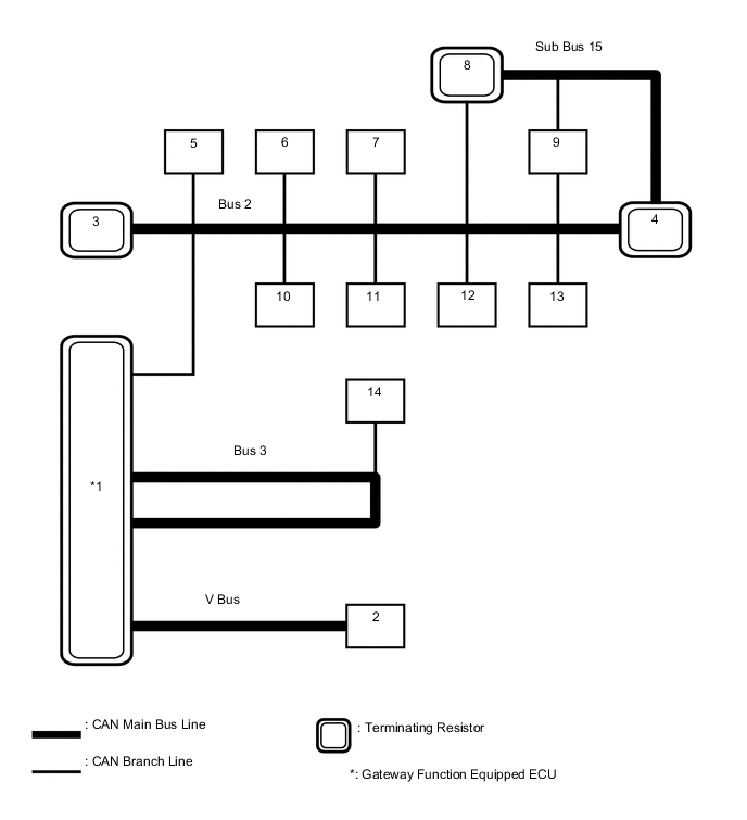
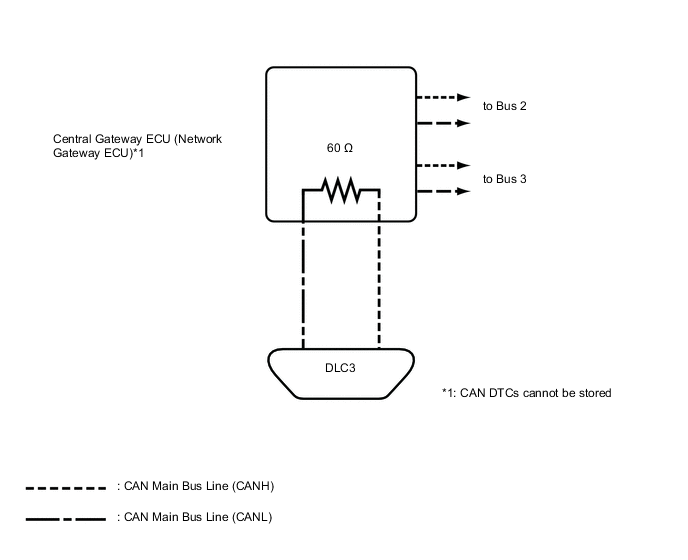
Text in Illustration 1 Central Gateway ECU (Network Gateway ECU)
(for Bus 2, Bus 3 and V Bus)
2 DLC3
(for V Bus)
3 Combination Meter Assembly
(for Bus 2)
4 ECM
(for Bus 2 and Sub Bus 15)
5 Smart Key ECU Assembly (Certification ECU)*1
(for Bus 2)
6 Spiral Cable with Sensor Sub-assembly (Steering Sensor)
(for Bus 2)
7 Pre-crash Safety City Sensor
(for Bus 2)
8 Hybrid Vehicle Control ECU
(for Bus 2 and Sub Bus 15)
9 Brake Booster with Master Cylinder Assembly (Skid Control ECU)
(for Bus 2 and Sub Bus 15)
10 Airbag Sensor Assembly
(for Bus 2)
11 Power Steering ECU Assembly
(for Bus 2)
12 Air Conditioning Amplifier Assembly
(for Bus 2)
13 Main Body ECU (Multiplex Network Body ECU)
(for Bus 2)
14 Radio and Display Receiver Assembly*2
(for Bus 3)
-
*1: w/ Power Switch
-
*2: w/ Display
-
Tech Tips
Refer to the following bus wiring diagrams for details.
-
-
BUS 2
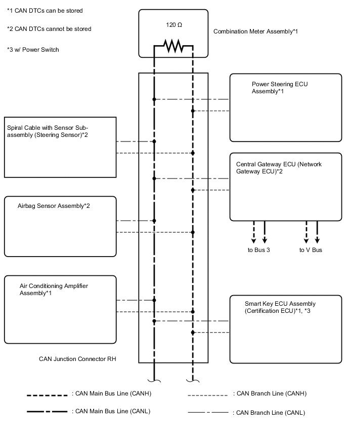
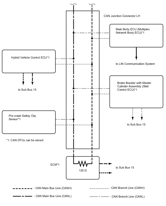
Tech Tips
The CAN communication system connects to other network via ECUs that function as a gateway Click here.
-
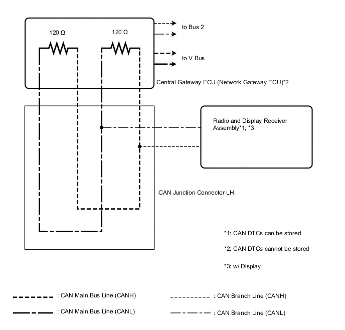
BUS 3
-
SUB BUS 15

-
V BUS