LIN COMMUNICATION SYSTEM, Diagnostic DTC:B2287
| DTC Code | DTC Name |
|---|---|
| B2287 | LIN Communication Master Malfunction |
DESCRIPTION
This DTC is stored when there is an open, short or ECU communication malfunction between the power management control ECU and certification ECU (smart key ECU assembly).
| DTC No. | DTC Detection Condition | Trouble Area |
|---|---|---|
| B2287 | There is an open, short or ECU communication malfunction between power management control ECU and certification ECU (smart key ECU assembly). |
|
WIRING DIAGRAM
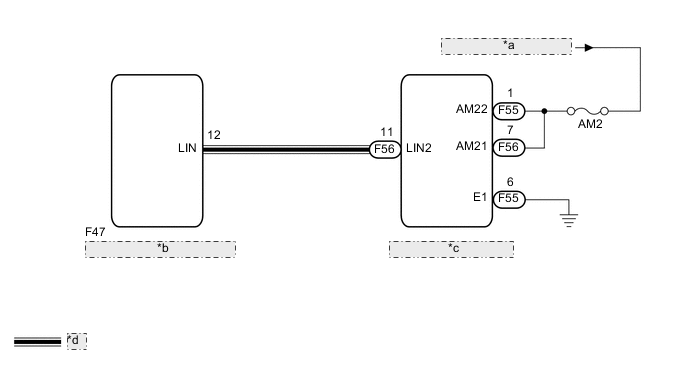
| *a | from Auxiliary Battery |
| *b | Certification ECU (Smart Key ECU Assembly) |
| *c | Power Management Control ECU |
| *d | LIN Communication Line |
CAUTION / NOTICE / HINT
Note
-
Inspect the fuses for circuits related to this system before performing the following inspection procedure.
-
If the certification ECU (smart key ECU assembly) or power management control ECU is replaced, refer to Service Bulletin.
-
When using the GTS to troubleshoot with the ignition switch off:
Connect the GTS to the DLC3, and turn the courtesy switch on and off at 1.5-second intervals until communication between the GTS and vehicle begins.
PROCEDURE
-
CHECK DTC OUTPUT
-
Clear the DTC Click here.
-
Recheck for DTCs.
Tech Tips
Check for both "Entry&Start" and "Power Source Control" DTCs.
Result Result Proceed to Only DTC B2287 is output. A DTC B2287 and B2785 are output simultaneously. B Tech Tips
When DTC B2287 and B2785 are output simultaneously, perform troubleshooting for DTC B2785 first.
B 
GO TO DTC B2785 Click here
A 
-
-
CHECK HARNESS AND CONNECTOR (POWER MANAGEMENT CONTROL ECU - AUXILIARY BATTERY AND BODY GROUND)
-
Disconnect the F55 and F56 power management control ECU connectors.
-
Measure the resistance and voltage according to the value(s) in the table below.
Standard Resistance Tester Connection Condition Specified Condition F55-6 (E1) - Body ground Always Below 1 Ω Standard Voltage Tester Connection Condition Specified Condition F55-1 (AM22) - Body ground Ignition switch off 11 to 14 V F56-7 (AM21) - Body ground Ignition switch off 11 to 14 V
NG
REPAIR OR REPLACE HARNESS OR CONNECTOR
OK
-
-
CHECK HARNESS AND CONNECTOR (CERTIFICATION ECU - POWER MANAGEMENT CONTROL ECU)
-
Disconnect the F47 certification ECU (smart key ECU assembly) connectors.
-
Measure the resistance according to the value(s) in the table below.
Standard Resistance Tester Connection Condition Specified Condition F56-11 (LIN2) - F47-12 (LIN) Always Below 1 Ω F56-11 (LIN2) - Body ground Always 10 kΩ or higher
NG
REPAIR OR REPLACE HARNESS OR CONNECTOR
OK
-
-
CHECK SMART ENTRY AND START SYSTEM (for Entry Function)
-
Check that the entry lock and unlock function operates normally Click here.
OK Entry lock and unlock function operates normally.
OK
REPLACE POWER MANAGEMENT CONTROL ECU (See page POWER DISTRIBUTION > POWER MANAGEMENT CONTROL ECU > REMOVAL)
NG
REPLACE CERTIFICATION ECU (SMART KEY ECU ASSEMBLY)
-