LIN COMMUNICATION SYSTEM, Diagnostic DTC:B2321
| DTC Code | DTC Name |
|---|---|
| B2321 | Driver Side Door ECU Communication Stop |
DESCRIPTION
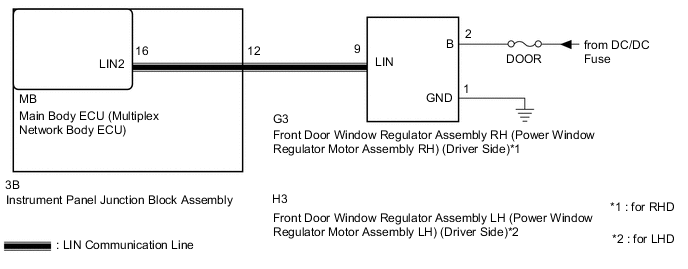
This DTC is stored when LIN communication between the front door window regulator assembly RH (power window regulator motor assembly RH) (driver side)*1 or front door window regulator assembly LH (power window regulator motor assembly LH) (driver side)*2 and main body ECU (multiplex network body ECU) stops for 10 seconds or more.
| DTC No. | DTC Detection Condition | Trouble Area |
|---|---|---|
| B2321 | No communication between the front door window regulator assembly RH (power window regulator motor assembly RH) (driver side)*1 or front door window regulator assembly LH (power window regulator motor assembly LH) (driver side)*2 and main body ECU (multiplex network Body ECU) for 10 seconds or more. |
|
*1 : for RHD
*2 : for LHD
WIRING DIAGRAM
CAUTION / NOTICE / HINT
Note
-
When a front door window regulator assembly (power window regulator motor assembly) is replaced or removed and reinstalled, it requires initialization Click here.
-
When using the GTS with the ignition switch off to troubleshoot:
Connect the GTS to the vehicle and turn a courtesy light switch on and off at 1.5-second intervals until communication between the GTS and vehicle begins.
-
Inspect the fuses and for circuits related to this system before performing the following inspection procedure.
Tech Tips
-
When communication between the front door window regulator assembly RH (power window regulator motor assembly RH) (driver side)*1 or front door window regulator assembly LH (power window regulator motor assembly LH) (driver side)*2 and main body ECU (multiplex network Body ECU) stops, DTC B2325 is also stored.
*1 : for RHD
*2 : for LHD
PROCEDURE
-
CLEAR DTC
-
Clear the DTCs Click here.
NEXT 
-
-
CHECK FOR DTC
-
Check for DTCs Click here.
Result Result Proceed to DTC B2321 is output A DTC B2321 and B2325 is output B Tech Tips
When both B2321 and B2325 are output at the same time, troubleshoot B2325 first.
B 
GO TO DIAGNOSTIC TROUBLE CODE CHART Click here
A
-
-
CHECK INSTRUMENT PANEL JUNCTION BLOCK ASSEMBLY
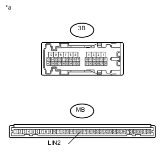
Text in Illustration *a Front view of wire harness connector
(to Instrument Panel Junction Block Assembly)
-
Remove the main body ECU (multiplex network Body ECU) from the instrument panel junction block assembly Click here.
-
Disconnect the 3B instrument panel junction block assembly connector.
-
Measure the resistance according to the value(s) in the table below.
Standard Resistance Tester Connection Condition Specified Condition MB-16 (LIN2) - 3B-12 Always Below 1 Ω MB-16 (LIN2) or 3B-12 - Body ground Always 10 kΩ or higher
NG
REPAIR OR REPLACE INSTRUMENT PANEL JUNCTION BLOCK ASSEMBLY Click here
OK
-
-
CHECK HARNESS AND CONNECTOR (INSTRUMENT PANEL JUNCTION BLOCK ASSEMBLY - POWER WINDOW REGULATOR MOTOR ASSEMBLY)
-
Disconnect the G3 front door window regulator assembly RH (power window regulator motor assembly RH) (driver side)*1 or H3 front door window regulator assembly LH (power window regulator motor assembly LH) (driver side)*2 connector.
-
Measure the resistance according to the value(s) in the table below.
Standard Resistance Tester Connection Condition Specified Condition 3B-12 - G3-9 (LIN)*1
3B-12 - H3-9 (LIN)*2
Always Below 1 Ω 3B-12 or G3-9 (LIN) - Body ground*1
3B-12 or H3-9 (LIN) - Body ground*2
Always 10 kΩ or higher *1 : for RHD
*2 : for LHD
NG
REPAIR OR REPLACE HARNESS OR CONNECTOR
OK
-
-
CHECK HARNESS AND CONNECTOR (POWER SOURCE CIRCUIT)
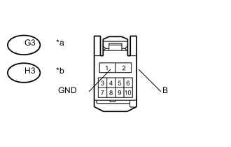
Text in Illustration *a Front view of wire harness connector
(to front door window regulator assembly RH (Power Window Regulator Motor Assembly RH) (Driver Side))*1
*b Front view of wire harness connector
(to front door window regulator assembly LH (Power Window Regulator Motor Assembly LH) (Driver Side))*2
-
Measure the resistance according to the value(s) in the table below.
Standard Resistance Tester Connection Condition Specified Condition G3-1 (GND) - Body ground*1
H3-1 (GND) - Body ground*2
Always Below 1 Ω -
Measure the voltage according to the value(s) in the table below.
Standard Voltage Tester Connection Condition Specified Condition G3-2 (B) - Body ground*1
H3-2 (B) - Body ground*2
Ignition switch off 11 to 14 V *1 : for RHD
*2 : for LHD
NG
REPAIR OR REPLACE HARNESS OR CONNECTOR (POWER SOURCE CIRCUIT)
OK
-
-
REPLACE FRONT DOOR WINDOW REGULATOR ASSEMBLY (FRONT POWER WINDOW REGULATOR MOTOR ASSEMBLY)
-
Replace the front door window regulator assembly RH (power window regulator motor assembly RH) (driver side)*1 or front door window regulator assembly LH (power window regulator motor assembly LH) (driver side)*2 Click here.
*1 : for RHD
*2 : for LHD
NEXT
-
-
CLEAR DTC
-
Clear the DTCs Click here.
NEXT
-
-
CHECK FOR DTC
-
Check for DTCs Click here.
Result Result Proceed to DTC B2321 is not output A DTC B2321 is output B
A
END (FRONT DOOR WINDOW REGULATOR ASSEMBLY (POWER WINDOW REGULATOR MOTOR ASSEMBLY) WAS DEFECTIVE
B
REPLACE MAIN BODY ECU (MULTIPLEX NETWORK BODY ECU) Click here
-