NAVIGATION SYSTEM, Diagnostic DTC:B15C3
| DTC Code | DTC Name |
|---|---|
| B15C3 | Speaker Output Short |
DESCRIPTION
This DTC is stored when a malfunction occurs in the speakers.
| DTC No. | DTC Detection Condition | Trouble Area |
|---|---|---|
| B15C3 | A short is detected in the speaker output circuit. |
|
-
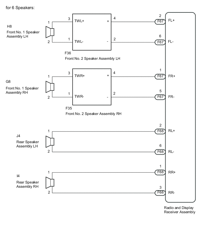
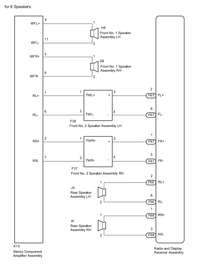
*1: for 8 Speakers
WIRING DIAGRAM
PROCEDURE
-
CONFIRM MODEL
Result Result Proceed to for 6 Speakers A for 8 Speakers B
B 
CHECK HARNESS AND CONNECTOR Click here
A 
-
CHECK HARNESS AND CONNECTOR
-
Disconnect the F67 and F68 radio and display receiver assembly connectors.
-
Disconnect the H8 and G8 front No. 1 speaker assembly connectors.
-
Disconnect the F36 and F35 front No. 2 speaker assembly connectors.
-
Disconnect the J4 and I4 rear speaker assembly connectors.
-
Measure the resistance between each of the radio and display receiver assembly and the front No. 2 speaker assembly to check for an open circuit in the wire harness.
Standard Resistance Tester Connection Condition Specified Condition F67-2 (FL+) - F36-4 (+) Always Below 1 Ω F67-6 (FL-) - F36-2 (-) Always Below 1 Ω F67-1 (FR+) - F35-4 (+) Always Below 1 Ω F67-5 (FR-) - F35-2 (-) Always Below 1 Ω -
Measure the resistance between each of the front No. 2 speaker assembly and front No. 1 speaker assembly to check for an open circuit in the wire harness.
Standard Resistance Tester Connection Condition Specified Condition F36-3 (TWL+) - H8-1 Always Below 1 Ω F36-1 (TWL-) - H8-2 Always Below 1 Ω F35-3 (TWR+) - G8-1 Always Below 1 Ω F35-1 (TWR-) - G8-2 Always Below 1 Ω -
Measure the resistance between each of the radio and display receiver assembly and the rear speaker assembly to check for an open circuit in the wire harness.
Standard Resistance Tester Connection Condition Specified Condition F68-2 (RL+) - J4-1 Always Below 1 Ω F68-6 (RL-) - J4-2 Always Below 1 Ω F68-1 (RR+) - I4-1 Always Below 1 Ω F68-3 (RR-) - I4-2 Always Below 1 Ω -
Measure the resistance between each speaker assembly and body ground to check for a short circuit in the wire harness.
Standard Resistance Tester Connection Condition Specified Condition H8-1 - Body ground Always 10 kΩ or higher H8-2 - Body ground Always 10 kΩ or higher G8-1 - Body ground Always 10 kΩ or higher G8-2 - Body ground Always 10 kΩ or higher F36-4 (+) - Body ground Always 10 kΩ or higher F36-2 (-) - Body ground Always 10 kΩ or higher F35-4 (+) - Body ground Always 10 kΩ or higher F35-2 (-) - Body ground Always 10 kΩ or higher J4-1 - Body ground Always 10 kΩ or higher J4-2 - Body ground Always 10 kΩ or higher I4-1 - Body ground Always 10 kΩ or higher I4-2 - Body ground Always 10 kΩ or higher
NG 
REPAIR OR REPLACE HARNESS OR CONNECTOR
OK
-
-
INSPECT FRONT NO. 1 SPEAKER ASSEMBLY
-
Inspect the front No. 1 speaker assembly Click here.
Tech Tips
The speaker should not be removed to check resistance.
NG
REPLACE FRONT NO. 1 SPEAKER ASSEMBLY Click here
OK
-
-
INSPECT FRONT NO. 2 SPEAKER ASSEMBLY
-
Check that the malfunction disappears when another speaker in good condition is installed.
OK Malfunction disappears. Tech Tips
-
Connect all the connectors to the front No. 2 speakers.
-
If there is a possibility that either the right or left front speaker is defective, inspect by interchanging the right one with the left one.
-
Perform the above inspection on both LH and RH sides.
-
NG
REPLACE FRONT NO. 2 SPEAKER ASSEMBLY Click here
OK
-
-
INSPECT REAR SPEAKER ASSEMBLY
-
Inspect the rear speaker assembly Click here.
Tech Tips
The speaker should not be removed to check resistance.
OK
REPLACE RADIO AND DISPLAY RECEIVER ASSEMBLY Click here
NG
REPLACE REAR SPEAKER ASSEMBLY Click here
-
-
CHECK HARNESS AND CONNECTOR
-
Disconnect the F67 and F68 radio and display receiver assembly connectors.
-
Disconnect the K15 stereo component amplifier assembly connector.
-
Disconnect the H8 and G8 front No. 1 speaker assembly connectors.
-
Disconnect the F38 and F37 front No. 2 speaker assembly connectors.
-
Disconnect the J4 and I4 rear speaker assembly connectors.
-
Measure the resistance between each of the stereo component amplifier assembly and front No. 1 speaker assembly to check for an open circuit in the wire harness.
Standard Resistance Tester Connection Condition Specified Condition K15-4 (WFL+) - H8-1 Always Below 1 Ω K15-11 (WFL-) - H8-2 Always Below 1 Ω K15-3 (WFR+) - G8-1 Always Below 1 Ω K15-8 (WFR-) - G8-2 Always Below 1 Ω -
Measure the resistance between each of the radio and display receiver assembly and the front No. 2 speaker assembly to check for an open circuit in the wire harness.
Standard Resistance Tester Connection Condition Specified Condition F67-2 (FL+) - F38-2 (+) Always Below 1 Ω F67-6 (FL-) - F38-4 (-) Always Below 1 Ω F67-1 (FR+) - F37-2 (+) Always Below 1 Ω F67-5 (FR-) - F37-4 (-) Always Below 1 Ω -
Measure the resistance between each of the stereo component amplifier assembly and front No. 2 speaker assembly to check for an open circuit in the wire harness.
Standard Resistance Tester Connection Condition Specified Condition K15-1 (RL+) - F38-1 (TWL+) Always Below 1 Ω K15-6 (RL-) - F38-3 (TWL-) Always Below 1 Ω K15-2 (RR+) - F37-1 (TWR+) Always Below 1 Ω K15-7 (RR-) - F37-3 (TWR-) Always Below 1 Ω -
Measure the resistance between each of the radio and display receiver assembly and the rear speaker assembly to check for an open circuit in the wire harness.
Standard Resistance Tester Connection Condition Specified Condition F68-2 (RL+) - J4-1 Always Below 1 Ω F68-6 (RL-) - J4-2 Always Below 1 Ω F68-1 (RR+) - I4-1 Always Below 1 Ω F68-3 (RR-) - I4-2 Always Below 1 Ω -
Measure the resistance between each speaker assembly and body ground to check for a short circuit in the wire harness.
Standard Resistance Tester Connection Condition Specified Condition H8-1 - Body ground Always 10 kΩ or higher H8-2 - Body ground Always 10 kΩ or higher G8-1 - Body ground Always 10 kΩ or higher G8-2 - Body ground Always 10 kΩ or higher F38-2 (+) - Body ground Always 10 kΩ or higher F38-4 (-) - Body ground Always 10 kΩ or higher F38-1 (TWL+)- Body ground Always 10 kΩ or higher F38-3 (TWL-) - Body ground Always 10 kΩ or higher F37-2 (+) - Body ground Always 10 kΩ or higher F37-4 (-) - Body ground Always 10 kΩ or higher F37-1 (TWR+)- Body ground Always 10 kΩ or higher F37-3 (TWR-) - Body ground Always 10 kΩ or higher J4-1 - Body ground Always 10 kΩ or higher J4-2 - Body ground Always 10 kΩ or higher I4-1 - Body ground Always 10 kΩ or higher I4-2 - Body ground Always 10 kΩ or higher
NG
REPAIR OR REPLACE HARNESS OR CONNECTOR
OK
-
-
INSPECT FRONT NO. 1 SPEAKER ASSEMBLY
-
Inspect the front No. 1 speaker assembly Click here.
Tech Tips
The speaker should not be removed to check resistance.
NG
REPLACE FRONT NO. 1 SPEAKER ASSEMBLY Click here
OK
-
-
INSPECT FRONT NO. 2 SPEAKER ASSEMBLY
-
Check that the malfunction disappears when another speaker in good condition is installed.
OK Malfunction disappears. Tech Tips
-
Connect all the connectors to the front No. 2 speakers.
-
If there is a possibility that either the right or left front speaker is defective, inspect by interchanging the right one with the left one.
-
Perform the above inspection on both LH and RH sides.
-
NG
REPLACE FRONT NO. 2 SPEAKER ASSEMBLY Click here
OK
-
-
INSPECT REAR SPEAKER ASSEMBLY
-
Inspect the rear speaker assembly Click here.
Tech Tips
The speaker should not be removed to check resistance.
NG
REPLACE REAR SPEAKER ASSEMBLY Click here
OK
-
-
REPLACE STEREO COMPONENT AMPLIFIER ASSEMBLY
-
Temporarily replace the stereo component amplifier assembly with a new or normally functioning one Click here.
-
Check that sound is emitted from the speaker normally.
OK Malfunction disappears.
OK
END (STEREO COMPONENT AMPLIFIER ASSEMBLY WAS DEFECTIVE)
NG
REPLACE RADIO AND DISPLAY RECEIVER ASSEMBLY Click here
-