STEERING COLUMN ASSEMBLY(for RHD) REASSEMBLY

PROCEDURE
-
INSTALL POWER STEERING MOTOR ASSEMBLY
Note
-
Do not drop the power steering motor assembly, strike it with tools or subject it to impacts.
-
If the power steering motor assembly is subjected to an impact, replace it with a new one.
-
Do not pull the wire harness and the tilt steering support bond cable of the power steering motor assembly.
-
Do not allow any moisture to come into contact with the power steering motor assembly.
-
Do not loosen any bolts not mentioned in the procedure.
-
Do not allow any foreign objects to contaminate the power steering motor assembly.
-
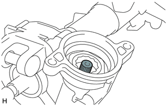
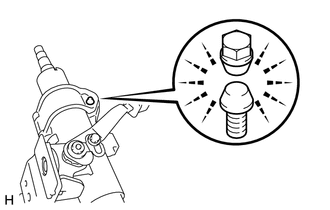
Apply grease to the serrated part of the electric power steering column sub-assembly.
Text in Illustration 
Grease Note
First wipe off the existing grease from the serrated part, and then apply the dedicated grease supplied with a new power steering motor assembly or electric power steering column sub-assembly.
-
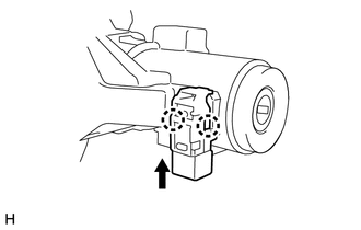
Using "TORX" socket wrench T40, temporarily install the power steering motor assembly to the electric power steering column sub-assembly with the 2 bolts.
Note
When temporarily installing the 2 bolts to the power steering motor assembly, do not tighten them all the way down.
-
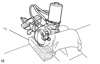
Text in Illustration *1 Wooden Block Secure the steering column assembly in a vise using aluminum plates and a piece of cloth.
Note
-
Do not overtighten the vise, as the steering column assembly may become deformed.
-
Secure the power steering motor assembly so that it is directly upright.
-
Support the steering column assembly with a wooden block or similar item to ensure that it does not fall.
-
-
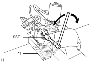
Text in Illustration *1 Wooden Block Using SST, turn the steering main shaft once 180 degrees to the left and then 180 degrees to the right at a speed of 60 rpm, and repeat 2 to 3 times to adjust the axis centering of the power steering motor assembly.
- SST
- 09616-00011
-
Using "TORX" socket wrench T40, tighten the 2 bolts.
- Torque:
- 19 N*m { 189 kgf*cm, 14 ft.*lbf }
-
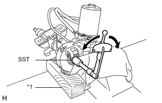
Text in Illustration *1 Wooden Block Using SST, measure the turning torque of the steering main shaft.
- SST
- 09616-00011
- Torque:
- Turning torque
- 1.45 N*m { 14.8 kgf*cm, 12.8 in.*lbf }
- or less
Note
Ensure that there is no abnormal resistance during rotation.
If the torque is not as specified, readjust the axis centering of the power steering motor assembly.
-
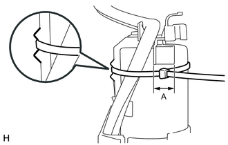
Install 2 new clamps and tape to the wire harness as shown in the illustration.
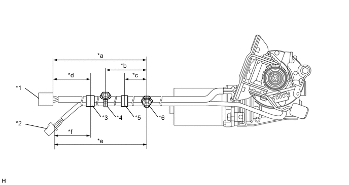
Text in Illustration *1 Power Steering Motor Wire Harness *2 Torque Sensor Wire Harness *3 Tape A *4 No. 3 Clamp *5 Tape B *6 No. 2 Clamp *a 358 to 378 mm (1.18 to 1.23 ft.) *b 152 to 168 mm (5.99 to 6.61 in.) *c 60 to 100 mm (2.37 to 3.93 in.) *d 80 to 120 mm (3.15 to 4.72 in.) *e 373 to 393 mm (1.23 to 1.28 ft.) *f 115 mm (4.53 in.) Note
Wrap the tape at least 1.5 turns.
-
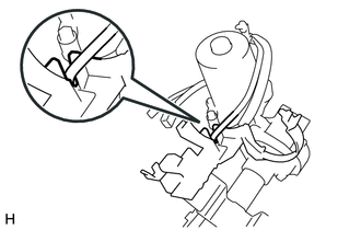
Pass the torque sensor wire harness through the cutout of a new protector.
-
Engage the clamp and install the protector to the steering column assembly.
Note
Make sure the wire harness is not pinched between the protector and the steering column assembly.
-
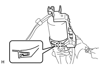
Engage the No. 2 clamp and install the wire harness to the protector.
-
Pass a new No. 1 clamp through the groove in the protector, and tighten it within area A shown in the illustration to secure the protector and the wire harness to the power steering motor assembly.
Note
Make sure there is no rattling or looseness in the protector.
Tech Tips
-
Fastening power for No. 1 clamp: 200 N (20 kgf, 45 lbf)
-
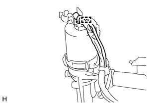
Coat the protector with paint.
-
-
Cut off the excess length of No. 1 clamp.
-
-
INSTALL IGNITION OR STARTER SWITCH ASSEMBLY (w/o Power Switch)
-
Engage the 2 claws to install the ignition or starter switch assembly onto the upper steering column bracket assembly.
-
-
INSTALL IGNITION SWITCH LOCK CYLINDER ASSEMBLY (w/o Power Switch)
-
Turn the ignition switch to ACC.
-
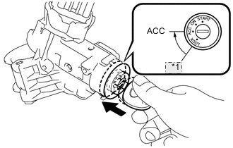
*1 LOCK Install the ignition switch lock cylinder assembly into the upper steering column bracket assembly.
Tech Tips
Make sure that the ignition switch lock cylinder assembly is securely fixed onto the ignition switch lock cylinder assembly.
-
-
INSTALL KEY INTER LOCK SOLENOID (w/o Power Switch)
-
Install the key inter lock solenoid onto the upper steering column bracket assembly with the 2 screws.
-
-
INSTALL UN-LOCK WARNING SWITCH ASSEMBLY (w/o Power Switch)
-
Engage the 2 claws to install the un-lock warning switch assembly onto the upper steering column bracket assembly.
Tech Tips
Slide the un-lock warning switch assembly, in the direction shown by the arrow in the illustration, to install it.
-
-
INSTALL UPPER STEERING COLUMN BRACKET WITH SWITCH ASSEMBLY (w/o Power Switch)
-
Fix the steering column assembly in a vise between aluminum plates.
Note
Do not overtighten the vise.
-
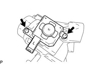
Install the upper steering column bracket with switch assembly with a new steering lock set bolt, and then tighten the bolt until its head comes off.
-
-
INSTALL STEERING LOCK ACTUATOR ASSEMBLY (w/ Power Switch)
Tech Tips
When replacing the steering lock actuator assembly, refer to Service Bulletin.
-
Fix the steering column assembly in a vise between aluminum plates.
Note
Do not overtighten the vise.
-
Install the steering lock actuator assembly with a new steering lock set bolt, and then tighten the bolt until its head comes off.
-