STEERING COLUMN ASSEMBLY(for LHD) INSTALLATION

PROCEDURE
-
INSTALL STEERING COLUMN ASSEMBLY
-
Install the steering column assembly to the instrument panel reinforcement assembly with the 2 nuts and bolt.
- Torque:
- Bolt
- 36 N*m { 367 kgf*cm, 27 ft.*lbf }
- Nut
- 25 N*m { 255 kgf*cm, 18 ft.*lbf }
Note
Be sure there is no interference around the wire harness.
-
Connect all the connectors and engage all the wire harness clamps to the steering column assembly.
-
Connect the 2 steering column assembly connectors to the power steering ECU assembly.
-
Engage the wire harness clamp to the power steering ECU assembly.
-
-
INSTALL BRAKE PEDAL SUPPORT SUB-ASSEMBLY
-
INSTALL STEERING INTERMEDIATE SHAFT ASSEMBLY
-
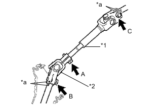
Align the matchmarks on the No. 2 steering intermediate shaft assembly and the steering column assembly and install it with the bolt C.
Text in Illustration *1 No. 2 Steering Intermediate Shaft Assembly *2 Steering Sliding Yoke Sub-assembly *a Matchmark - Torque:
- 35 N*m { 360 kgf*cm, 26 ft.*lbf }
Tech Tips
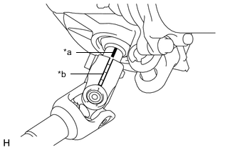
When either the steering column assembly or the steering intermediate shaft assembly is replaced with a new one, they have no matchmarks, so align the marking (pink) on the steering column assembly shaft with the slit of the No. 2 steering intermediate shaft assembly, and install them.
Text in Illustration *a Marking (Pink) *b Slit -
Align the matchmarks on steering sliding yoke sub-assembly and the steering link assembly.
Tech Tips
When the steering intermediate shaft assembly is replaced with a new one, it has no matchmarks, so install it while the head of the bolt B faces the back of the vehicle.
-
Install bolt B.
- Torque:
- 35 N*m { 360 kgf*cm, 26 ft.*lbf }
-
Tighten bolt A.
- Torque:
- 35 N*m { 360 kgf*cm, 26 ft.*lbf }
-
-
INSTALL COLUMN HOLE COVER SILENCER SHEET
-
Install the column hole cover silencer sheet with the 2 clips.
-
-
INSTALL TRANSPONDER KEY AMPLIFIER (w/o Power Switch)
-
INSTALL COMBINATION SWITCH ASSEMBLY
-
Install the combination switch assembly to the steering column assembly with the clamp.
-
Connect all the connectors to the combination switch assembly.
-
-
INSTALL UPPER STEERING COLUMN COVER
-
Engage the claw to install the upper steering column cover.
-
-
INSTALL LOWER STEERING COLUMN COVER
-
Engage the 4 claws to install the lower steering column cover.
-
Install the 3 screws.
-
-
INSTALL STEERING COLUMN COVER SUPPORT (w/ Power Switch)
-
Engage the 4 claws and install the steering column cover support.
-
-
POSITION FRONT WHEELS FACING STRAIGHT AHEAD
-
ADJUST SPIRAL CABLE
-
INSTALL STEERING WHEEL ASSEMBLY
-
INSTALL STEERING PAD
-
CONNECT CABLE TO NEGATIVE AUXILIARY BATTERY TERMINAL
-
INSPECT SRS WARNING LIGHT
-
PERFORM CALIBRATION OF TORQUE SENSOR ZERO POINT