STEERING COLUMN ASSEMBLY(for LHD) REMOVAL

CAUTION / NOTICE / HINT
CAUTION:
Some of these service operations affect the SRS airbag system. Read the precautionary notices concerning the SRS airbag system before servicing Click here.
PROCEDURE
-
PRECAUTION
Note
After turning the ignition switch off, waiting time may be required before disconnecting the cable from the negative (-) auxiliary battery terminal. Therefore, make sure to read the disconnecting the cable from the negative (-) auxiliary battery terminal notices before proceeding with work Click here.
-
POSITION FRONT WHEELS FACING STRAIGHT AHEAD
-
DISCONNECT CABLE FROM NEGATIVE AUXILIARY BATTERY TERMINAL
CAUTION:
Wait at least 90 seconds after disconnecting the cable from the negative (-) auxiliary battery terminal to disable the SRS system.
-
REMOVE STEERING PAD
-
REMOVE STEERING WHEEL ASSEMBLY
-
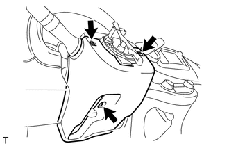
REMOVE STEERING COLUMN COVER SUPPORT (w/ Power Switch)
-
Disengage the 4 claws and remove the steering column cover support.
-
-
REMOVE LOWER STEERING COLUMN COVER
-
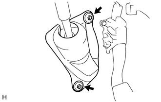
Remove the 3 screws.
-
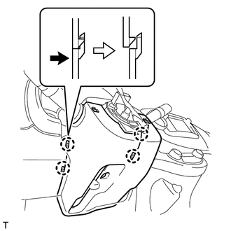
Disengage the 4 claws and remove the lower steering column cover.
-
-
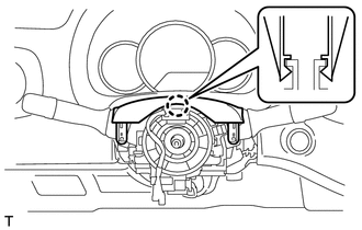
REMOVE UPPER STEERING COLUMN COVER
-
Disengage the claw and remove the upper steering column cover.
-
-
REMOVE COMBINATION SWITCH ASSEMBLY
-
Disconnect all the connectors from the combination switch assembly.
-
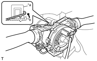
Text in Illustration *a Loosen The Clamp *b Raise The Claw Use pliers to hold the clamp and raise the claw with a screwdriver. Remove the combination switch assembly from the steering column assembly.
-
-
REMOVE TRANSPONDER KEY AMPLIFIER (w/o Power Switch)
-
REMOVE COLUMN HOLE COVER SILENCER SHEET
-
Remove the 2 clips and the column hole cover silencer sheet.
-
-
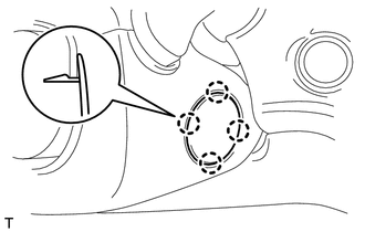
REMOVE STEERING INTERMEDIATE SHAFT ASSEMBLY
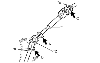
Text in Illustration *1 No. 2 Steering Intermediate Shaft Assembly *2 Steering Sliding Yoke Sub-assembly *a Matchmark
-
Place matchmarks on the No. 2 steering intermediate shaft assembly and the steering column assembly.
-
Place matchmarks on the steering sliding yoke sub-assembly and the steering link assembly.
-
Loosen bolt A.
-
Remove bolt B, bolt C and the steering intermediate shaft assembly.
-
-
REMOVE BRAKE PEDAL SUPPORT SUB-ASSEMBLY
-
REMOVE STEERING COLUMN ASSEMBLY
-
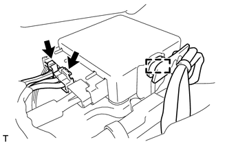
Disengage the wire harness clamp from the power steering ECU assembly.
-
Disconnect the 2 steering column assembly connectors from the power steering ECU assembly.
-
Disconnect all the connectors and disengage all the wire harness clamps from the steering column assembly.
-
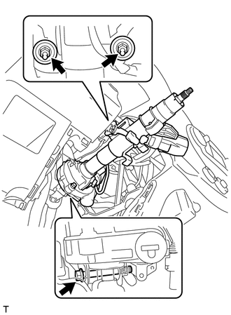
Remove the bolt, 2 nuts and the steering column assembly from the instrument panel reinforcement assembly.
-