POWER STEERING SYSTEM, Diagnostic DTC:C1513
| DTC Code | DTC Name |
|---|---|
| C1513 | Torque Sensor Deviation Excessive |
DESCRIPTION
The power steering ECU assembly supplies a voltage of 5 V to the torque sensor (steering column sub-assembly) and monitors the voltage value of the Hall IC inside the torque sensor (steering column sub-assembly) which changes in response to changes in the magnetic flux density (steering torque) detected by the Hall IC, and calculates the assist torque.
The Hall IC is a duplex system, and the power steering ECU assembly monitors the total value of TRQ1 (Hall IC 1) voltage and TRQ2 (Hall IC 2) voltage to detect malfunctions in the torque sensor (steering column sub-assembly).
While DTC C1513 is detected, power assist is stopped due to fail-safe operation.
| DTC No. | Detection Item | DTC Detection Condition | Trouble Area | Warning Indicate | Return-to-normal Condition |
|---|---|---|---|---|---|
| C1512 | Torque Sensor Deviation Excessive | Deviation of torque sensor TRQ1 and TRQ2 exceeds specified values | Torque sensor (Steering column sub-assembly) | EPS warning light: Comes on | Ignition switch ON again |
WIRING DIAGRAM
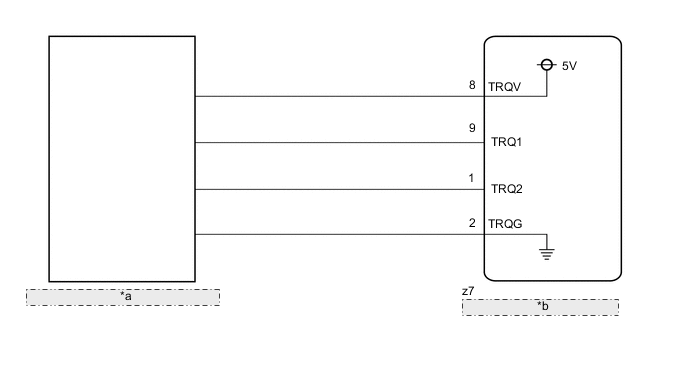
| *a | Torque Sensor (Steering Column Sub-assembly) |
| *b | Power Steering ECU Assembly |
CAUTION / NOTICE / HINT
Note
If the steering column sub-assembly has been replaced, perform torque sensor zero point calibration.
PROCEDURE
-
CHECK FOR DTC
-
Check for DTCs.
OK DTC C1511 and C1512 are not output. Result Result Proceed to DTCs C1511 and C1512 are not output A DTC C1511 is output B DTC C1512 is output C
B 
GO TO DTC C1511 Click here
C
GO TO DTC C1512 Click here
A 
-
-
CLEAR DTC
-
Clear the DTCs.
NEXT
-
-
CONFIRM DTC
-
Start the engine.
-
With the vehicle stopped, turn the steering wheel all the way to the left and right.
Tech Tips
Turn the wheel both strongly and gently when steering back and forth.
-
Check for DTCs.
OK DTC C1513 is not output. Result Result Proceed to OK A NG (for LHD) B NG (for RHD) C
A
USE SIMULATION METHOD TO CHECK Click here
B
REPLACE STEERING COLUMN SUB-ASSEMBLY Click here
C
REPLACE STEERING COLUMN SUB-ASSEMBLY Click here
-