POWER STEERING SYSTEM, Diagnostic DTC:C1512
| DTC Code | DTC Name |
|---|---|
| C1512 | Torque Sensor2 |
DESCRIPTION
The power steering ECU assembly supplies a voltage of 5 V to the torque sensor (steering column sub-assembly) and monitors the voltage value of the Hall IC inside the torque sensor (steering column sub-assembly) which changes in response to changes in the magnetic flux density (steering torque) detected by the Hall IC, and calculates the assist torque.
While DTC C1512 is detected, power assist is stopped due to fail-safe operation.
| DTC No. | Detection Item | DTC Detection Condition | Trouble Area | Warning Indicate | Return-to-normal Condition |
|---|---|---|---|---|---|
| C1512 | Torque Sensor2 | Diagnosis Condition: IG ON Malfunction Status: TRQ2 voltage is less than 0.25 V or more than 4.6 V |
|
EPS warning light: Comes on | Ignition switch ON again |
WIRING DIAGRAM
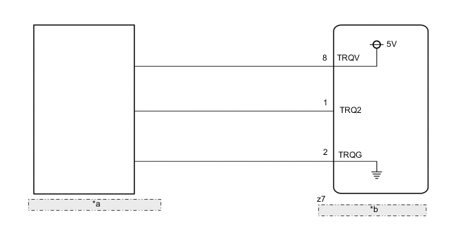
| *a | Torque Sensor (Steering Column Sub-assembly) |
| *b | Power Steering ECU Assembly |
CAUTION / NOTICE / HINT
Note
-
If the steering column sub-assembly has been replaced, perform torque sensor zero point calibration.
-
If the power steering ECU assembly has been replaced, perform assist map writing and torque sensor zero point calibration.
PROCEDURE
-
CHECK POWER STEERING ECU ASSEMBLY (TRQ2 VOLTAGE)
-
*a Component without harness connected
(Torque Sensor (Steering Column Sub-assembly))
Disconnect the power steering ECU assembly connector.
-
Connect 3 new 1.5 V batteries in series to prepare a 4.5 V power supply.
Tech Tips
Check that the voltage of the prepared power supply is 4.5 V.
-
Measure the voltage according to the value(s) in the table below.
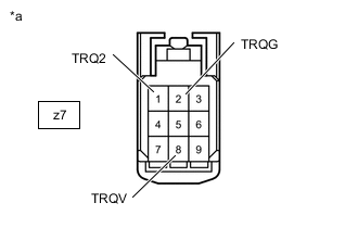
Standard Voltage Tester Connection Condition Specified Condition z7-1(TRQ2) - z7-2(TRQG)
-
Connect the 4.5 V positive (+) terminal to z7-8 (TRQV) and 4.5 V negative (-) terminal to z7-2 (TRQG)
-
Steering wheel not being turned (without load)
2.07 to 2.43 V
-
Connect the 4.5 V positive (+) terminal to z7-8 (TRQV) and 4.5 V negative (-) terminal to z7-2 (TRQG)
-
Steering wheel being turned to right with vehicle stopped
1.08 to 2.25 V
-
Connect the 4.5 V positive (+) terminal to z7-8 (TRQV) and 4.5 V negative (-) terminal to z7-2 (TRQG)
-
Steering wheel being turned to left with vehicle stopped
2.25 to 3.42 V Note
To avoid damaging the torque sensor (steering column assembly), do not apply a voltage of more than 5 V.
Tech Tips
-
The voltage values specified above are applicable when using an applied voltage of 4.5 V, and vary depending on the applied voltage (When compared to values for an applied voltage of 5 V, these values differ by a factor of 0.9).
-
When using an applied voltage of 5 V, the specified values are as follows.
Condition Specified Condition Steering wheel not being turned (without load) 2.3 to 2.7 V Steering wheel being turned to right with vehicle stopped 1.2 to 2.5 V Steering wheel being turned to left with vehicle stopped 2.5 to 3.8 V
Result Result Proceed to OK (for LHD) A OK (for RHD) B NG (for LHD) C NG (for RHD) D -
A 
REPLACE POWER STEERING ECU ASSEMBLY Click here
B
REPLACE POWER STEERING ECU ASSEMBLY Click here
C
REPLACE STEERING COLUMN SUB-ASSEMBLY Click here
D
REPLACE STEERING COLUMN SUB-ASSEMBLY Click here
-