POWER STEERING SYSTEM TERMINALS OF ECU
-
CHECK POWER STEERING ECU ASSEMBLY
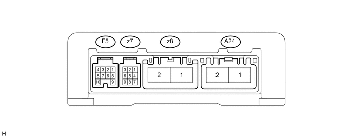
Terminal No. (Symbol) Wiring Color Terminal Description Condition Specified Condition A24-1 (PIG) - A24-2 (PGND) W - W-B EPS fuse Always 9 to 16 V A24-2 (PGND) - Body ground W-B - Body ground Body ground Always Below 1 Ω z8-1 (M1) - A24-2 (PGND) R - W-B Power steering motor
-
Ignition switch ON (READY)
-
Turn steering wheel to left
6 to 11 V
-
Ignition switch ON (READY)
-
Turn steering wheel to right
9 to 16 V z8-2 (M2) - A24-2 (PGND) B - W-B Power steering motor
-
Ignition switch ON (READY)
-
Turn steering wheel to left
9 to 16 V
-
Ignition switch ON (READY)
-
Turn steering wheel to right
6 to 11 V F5-7 (CANH) - F5-8 (CANL) LG - W CAN BUS Ignition switch off 54 to 69 Ω F5-1 (IG) - A24-2 (PGND) Y - W-B ECU-IG NO. 2 fuse Ignition switch ON (IG) 9 to 16 V F5-6 (TS) - A24-2 (PGND) G - W-B Test mode signal Always 9 to 16 V z7-9 (TRQ1) - A24-2 (PGND) W - W-B Torque sensor Ignition switch ON (READY), steering wheel not turned (without load) 2.3 to 2.7 V Ignition switch ON (READY), steering wheel turned to right with vehicle stopped 2.5 to 3.8 V Ignition switch ON (READY), steering wheel turned to left with vehicle stopped 1.2 to 2.5 V z7-8 (TRQV) - A24-2 (PGND) R - W-B Torque sensor Ignition switch ON (READY) 4.5 to 5.5 V z7-1 (TRQ2) - A24-2 (PGND) Y - W-B Torque sensor Ignition switch ON (READY), steering wheel not turned (without load) 2.3 to 2.7 V Ignition switch ON (READY), steering wheel turned to right with vehicle stopped 1.2 to 2.5 V Ignition switch ON (READY), steering wheel turned to left with vehicle stopped 2.5 to 3.8 V z7-2 (TRQG) - A24-2 (PGND) B - W-B Torque sensor Always Below 1 Ω -