BRAKE BOOSTER PUMP(for LHD) INSTALLATION
PROCEDURE
-
INSTALL BRAKE ACTUATOR BRACKET ASSEMBLY
-
Engage the clamp to install the frame wire to the brake actuator bracket assembly.
-
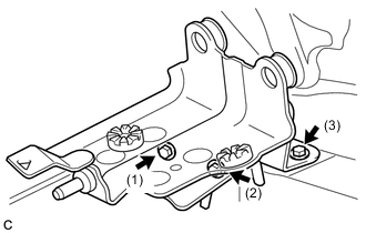
Install the brake actuator bracket assembly with the 3 bolts in the order shown in the illustration.
- Torque:
- 19 N*m { 194 kgf*cm, 14 ft.*lbf }
Note
Do not kink or damage the brake lines.
-
Engage the 2 clamps to install the frame wire to the brake actuator bracket assembly.
-
-
INSTALL ENGINE UNDER COVER LH
-
INSTALL FRONT WHEEL LH
- Torque:
- 103 N*m { 1050 kgf*cm, 76 ft.*lbf }
-
INSTALL BRAKE BOOSTER PUMP ASSEMBLY
-
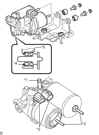
Text in Illustration *1 Union *2 Connector *3 Stud *4 Brake Booster Pump Collar *5 Brake Booster Pump Bushing *6 Brake Actuator Bracket Cushion Install the brake booster pump assembly to the brake actuator bracket assembly with the 2 brake booster pump bushings, 2 brake actuator case collars and the 2 nuts.
- Torque:
- 5.4 N*m { 55 kgf*cm, 48 in.*lbf }
Note
-
Do not carry the brake booster pump assembly by the parts shown in bold (*1, *2 and *3) in the illustration.
-
Do not drop the brake booster pump assembly when carrying it. If the brake booster pump assembly has been dropped, replace it with a new one.
-
Do not kink or damage the brake lines. If they are damaged, replace them with new ones.
-
Be careful not to allow any brake fluid to enter the connector.
-
When installing the brake booster pump assembly to the brake actuator bracket assembly, confirm that the brake booster pump collar*4 and the brake booster pump bushing*5 are installed on the brake booster pump assembly, and the 2 brake actuator bracket cushions*6 are installed on the brake actuator bracket assembly.
-
If installing a new brake booster pump assembly, do not remove the hole plug before connecting the brake lines because the brake booster pump assembly is filled with brake fluid.
-
Connect the 2 connectors to the brake booster pump assembly.
-
-
INSTALL NO. 1 BRAKE TUBE CLAMP BRACKET
-
Install the No. 1 brake tube clamp bracket to the brake booster pump assembly with the bolt.
- Torque:
- 7.0 N*m { 71 kgf*cm, 62 in.*lbf }
-
-
INSTALL FRONT NO. 1 BRAKE TUBE
-
Temporarily tighten the union nut of the front No. 1 brake tube to the brake booster pump assembly.
-
Install the bolt to secure the front No. 1 brake tube to the No. 1 brake tube clamp bracket.
- Torque:
- 7.0 N*m { 71 kgf*cm, 62 in.*lbf }
-
Using a union nut wrench 10 mm, fully tighten the front No. 1 brake tube.
- Torque:
- 15 N*m { 155 kgf*cm, 11 ft.*lbf }
Note
Use the formula to calculate special torque values for situations where the union nut wrench is combined with a torque wrench Click here.
-
-
INSTALL BRAKE ACTUATOR HOSE
-
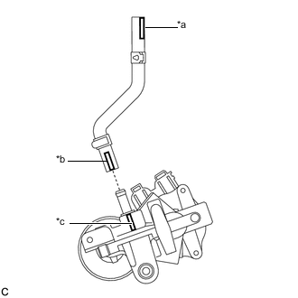
Text in Illustration *a Identification Mark (Red) *b Identification Mark (Yellowish Green) *c Rib (Unpainted) Connect the brake actuator hose to the brake booster pump assembly.
Note
-
Make sure that the identification mark (yellowish green) on the brake actuator hose is positioned within 30° of the brake booster pump rib.
-
Make sure to install the hose to the proper location.
-
-
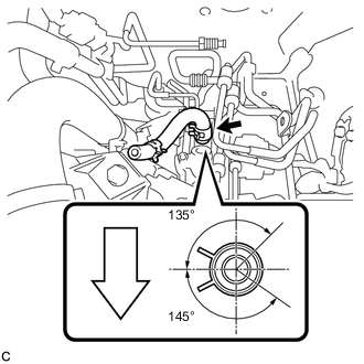
Move the clip to secure the brake actuator hose.
Text in Illustration 
Front of Vehicle Note
Install the clip within the range shown in the illustration.
-
-
INSTALL BRAKE BOOSTER WITH MASTER CYLINDER ASSEMBLY