BRAKE PEDAL(for LHD) INSTALLATION
PROCEDURE
-
INSTALL BRAKE PEDAL SUPPORT SUB-ASSEMBLY
-
Install the brake pedal support sub-assembly with the 4 nuts.
- Torque:
- 9.0 N*m { 92 kgf*cm, 80 in.*lbf }
-
Engage the wire harness clamp to the brake pedal support sub-assembly.
-
Install the bolt to secure the brake pedal support sub-assembly to the instrument panel reinforcement assembly.
- Torque:
- 24 N*m { 241 kgf*cm, 17 ft.*lbf }
-
Engage the wire harness clamp to the brake pedal support sub-assembly.
-
-
INSTALL PUSH ROD PIN
-
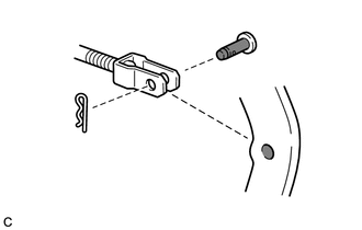
Apply lithium soap base glycol grease to the push rod pin and installation hole of the brake pedal sub-assembly.
Text in Illustration 
Lithium Soap Base Glycol Grease -
Install the push rod pin and a new clip to connect the push rod clevis to the brake pedal support sub-assembly.
Note
Insert the push rod pin in the correct direction.
-
-
INSTALL BRAKE PEDAL RETURN SPRING
-
Install the brake pedal return spring to the brake pedal support sub-assembly and the push rod pin.
-
-
PLACE FRONT WHEELS FACING STRAIGHT AHEAD
-
INSTALL STEERING INTERMEDIATE SHAFT ASSEMBLY
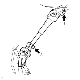
Text in Illustration *a Matchmark
-
Align the matchmarks on the steering intermediate shaft assembly and the steering column assembly and install it with the bolt B.
- Torque:
- 35 N*m { 360 kgf*cm, 26 ft.*lbf }
-
Tighten bolt A.
- Torque:
- 35 N*m { 360 kgf*cm, 26 ft.*lbf }
-
-
INSTALL COLUMN HOLE COVER SILENCER SHEET
-
INSTALL STOP LIGHT SWITCH MOUNTING ADJUSTER
-
Install the stop light switch mounting adjuster to the brake pedal support sub-assembly.
-
-
INSTALL STOP LIGHT SWITCH ASSEMBLY
-
INSTALL COMBINATION METER ASSEMBLY
-
INSTALL BRAKE PEDAL STROKE SENSOR ASSEMBLY
-
INSPECT AND ADJUST BRAKE PEDAL