ELECTRONICALLY CONTROLLED BRAKE SYSTEM, Diagnostic DTC:C1380/64

| DTC Code | DTC Name |
|---|---|
| C1380/64 | Stop Light Control Relay Malfunction |
DESCRIPTION
Upon receiving the hill-start assist control operating signal from the skid control ECU, the relay contact turns on and the stop lights come on.
| DTC No. | INF Code | DTC Detection Condition | Trouble Area |
|---|---|---|---|
| C1380/64 | 761 | When the voltage at the IG1 terminal is 9.5 V or more and the stop light control relay drive output (STP0) is ON, a signal is not input to the STP2 terminal for 2 seconds or more. |
|
| ↑ | 762 | When the voltage at the IG1 terminal is 9.5 V or more and the stop light control relay drive output (STP0) is OFF, the signal at the STP terminal is different from the input signal at the STP2 for 5 seconds or more. | ↑ |
-
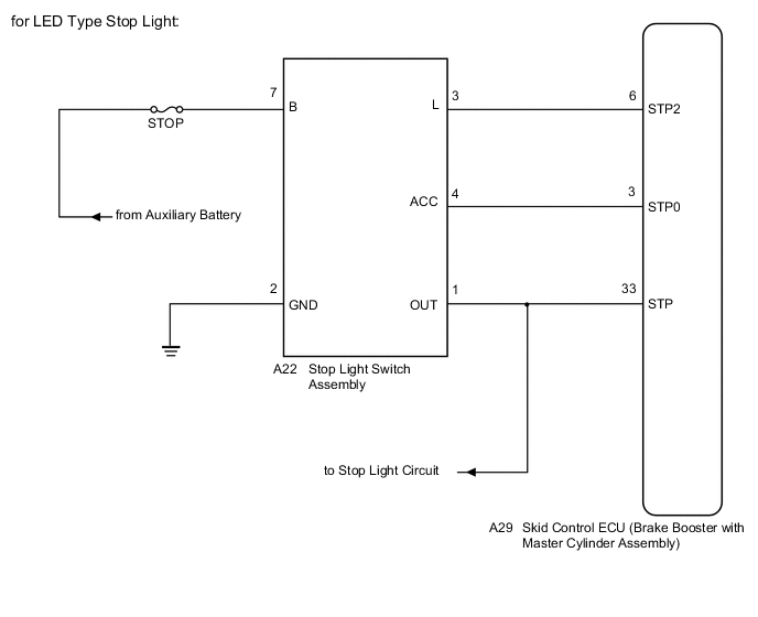
*1: for LED Type Stop Light
-
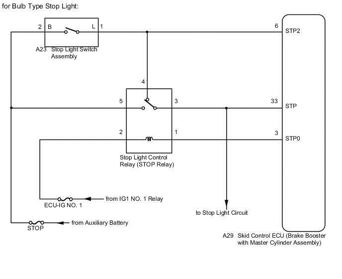
*2: for Bulb Type Stop Light
WIRING DIAGRAM
CAUTION / NOTICE / HINT
Note
-
When replacing the skid control ECU (brake booster with master cylinder assembly), perform initialization and calibration of the linear solenoid valve Click here.
-
Inspect the fuses for circuits related to this system before performing the following inspection procedure.
Tech Tips
When C1249/49 is output together with C1380/64, inspect and repair the trouble areas indicated by C1249/49 first Click here.
PROCEDURE
-
CHECK STOP LIGHT OPERATION
-
Check that the stop lights come on when the brake pedal is depressed and go off when the brake pedal is released.
OK Condition Illumination Condition Brake pedal depressed. ON Brake pedal released. OFF
NG 
INSPECT LIGHTING SYSTEM (PROBLEM SYMPTOMS TABLE) Click here
OK 
-
-
READ VALUE USING GTS (STOP LIGHT SWITCH ASSEMBLY)
-
Connect the GTS to the DLC3.
-
Turn the ignition switch to ON (IG).
-
Select the Data List on the GTS Click here.
ABS/VSC/TRC Tester Display Measurement Item/Range Normal Condition Diagnostic Note Stop Light SW Stop light switch assembly / ON or OFF ON: Brake pedal depressed
OFF: Brake pedal released
- -
Check that the stop light switch assembly condition observed on the GTS changes according to brake pedal operation.
OK The GTS displays ON or OFF according to brake pedal operation.
NG 
CHECK HARNESS AND CONNECTOR (STP2 TERMINAL) Click here
OK
-
-
PERFORM ACTIVE TEST USING GTS (Stop Light Relay)
-
Select the Active Test on the GTS Click here.
ABS/VSC/TRC Tester Display Test Part Control Range Diagnostic Note Stop Light Relay Stop light control relay (Stop light switch assembly)*1
Stop light control relay (STOP relay)*2
Relay (Switch) ON/OFF Stop lights come on -
Perform the Active Test of the stop light control relay (stop light switch assembly)*1 or Stop light control relay (STOP relay)*2 using the GTS.
-
Select the Data List on the GTS Click here.
ABS/VSC/TRC Tester Display Measurement Item/Range Normal Condition Diagnostic Note Stop Light Relay Output Stop light control relay (Stop light switch assembly)*1
Stop light control relay (STOP relay)*2 output / ON or OFF
ON: Relay output on
OFF: Relay output off
- -
Check for stop light control relay (stop light switch assembly)*1 or Stop light control relay (STOP relay)*2 operation using the Data List and stop light operation by performing an Active Test.
-
*1: for LED Type Stop Light
-
*2: for Bulb Type Stop Light
Result Result Proceed to Data List content and stop light operation are normal. A Data List content and stop light operation are abnormal or Data List content is normal but stop lights do not turn on or off (for LED Type Stop Light). B Data List content and stop light operation are abnormal or Data List content is normal but stop lights do not turn on or off (for Bulb Type Stop Light). C -
B
INSPECT STOP LIGHT SWITCH ASSEMBLY Click here
C
CHECK HARNESS AND CONNECTOR (POWER SOURCE TERMINAL) Click here
A
-
-
CHECK HARNESS AND CONNECTOR (STP TERMINAL)
-
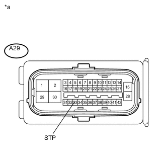
Text in Illustration *a Front view of wire harness connector
(to Skid Control ECU (Brake Booster with Master Cylinder Assembly))
Turn the ignition switch off.
-
Make sure that there is no looseness at the locking part and the connecting part of the connector.
-
Disconnect the skid control ECU (brake booster with master cylinder assembly) connector.
-
Measure the voltage according to the value(s) in the table below.
Standard Voltage Tester Connection Switch Condition Specified Condition A29-33 (STP) - Body ground Stop light switch assembly ON (Brake pedal depressed) 11 to 14 V A29-33 (STP) - Body ground Stop light switch assembly OFF (Brake pedal released) Below 1.5 V
NG
REPAIR OR REPLACE HARNESS OR CONNECTOR (STP2 CIRCUIT)
OK
-
-
RECONFIRM DTC
-
Reconnect the skid control ECU (brake booster with master cylinder assembly) connector.
-
Clear the DTCs Click here.
-
Turn the ignition switch to ON (READY).
-
Perform a road test.
-
Check if the same DTC is output Click here.
Result Result Proceed to DTC C1380/64 is not output. A DTC C1380/64 is output (for LHD). B DTC C1380/64 is output (for RHD). C
A
CHECK FOR INTERMITTENT PROBLEMS Click here
B
REPLACE BRAKE BOOSTER WITH MASTER CYLINDER ASSEMBLY Click here
C
REPLACE BRAKE BOOSTER WITH MASTER CYLINDER ASSEMBLY Click here
-
-
INSPECT STOP LIGHT SWITCH ASSEMBLY
-
Check the stop light control relay (stop light switch assembly) Click here.
OK The stop light control relay (stop light switch assembly) is normal. Result Result Proceed to NG A OK B
A
REPLACE STOP LIGHT SWITCH ASSEMBLY Click here
B
CHECK HARNESS AND CONNECTOR (STP0 TERMINAL) Click here
-
-
CHECK HARNESS AND CONNECTOR (POWER SOURCE TERMINAL)
-
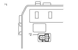
Text in Illustration *1 No. 2 Engine Room Relay Block *2 Stop Light Control Relay (STOP Relay) Turn the ignition switch off.
-
Remove the stop light control relay (STOP relay).
-
Measure the voltage according to the value(s) in the table below.
Standard Voltage Tester Connection Switch Condition Specified Condition Stop light control relay (STOP relay) terminal 5 - Body ground Always 11 to 14 V Stop light control relay (STOP relay) terminal 2 - Body ground Ignition switch ON (IG) 11 to 14 V
NG
REPAIR OR REPLACE HARNESS OR CONNECTOR (POWER SOURCE CIRCUIT)
OK
-
-
INSPECT STOP LIGHT CONTROL RELAY (STOP RELAY)
-
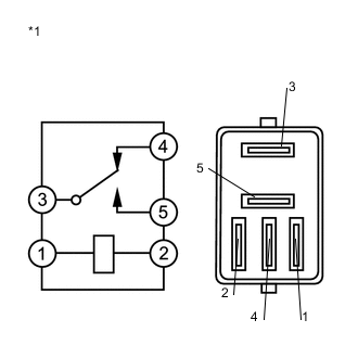
Text in Illustration *1 Stop Light Control Relay (STOP Relay) Measure the resistance according to the value(s) in the table below.
Standard Resistance Tester Connection Condition Specified Condition 3 - 4 Battery voltage not applied Below 1 Ω 3 - 5 Battery voltage not applied 10 kΩ or higher 3 - 4 Battery voltage applied to terminals 1 and 2 10 kΩ or higher 3 - 5 Battery voltage applied to terminals 1 and 2 Below 1 Ω
NG
REPLACE STOP LIGHT CONTROL RELAY (STOP RELAY)
OK
-
-
CHECK HARNESS AND CONNECTOR (STP0 TERMINAL)
-
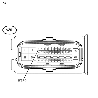
Text in Illustration *a Front view of wire harness connector
(to Skid Control ECU (Brake Booster with Master Cylinder Assembly))
Make sure that there is no looseness at the locking part and the connecting part of the connectors.
-
Disconnect the skid control ECU (brake booster with master cylinder assembly) connector.
-
Turn the ignition switch to ON (IG).
-
Measure the voltage according to the value(s) in the table below.
Standard Voltage Tester Connection Switch Condition Specified Condition A29-3 (STP0) - Body ground Ignition switch ON (IG) 11 to 14 V Result Result Proceed to OK (for LHD) A OK (for RHD) B NG C
A
REPLACE BRAKE BOOSTER WITH MASTER CYLINDER ASSEMBLY Click here
B
REPLACE BRAKE BOOSTER WITH MASTER CYLINDER ASSEMBLY Click here
C
REPAIR OR REPLACE HARNESS OR CONNECTOR (STP0 CIRCUIT)
-
-
CHECK HARNESS AND CONNECTOR (STP2 TERMINAL)
-
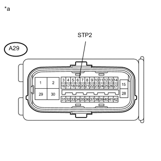
Text in Illustration *a Front view of wire harness connector
(to Skid Control ECU (Brake Booster with Master Cylinder Assembly))
Turn the ignition switch off.
-
Make sure that there is no looseness at the locking part and the connecting part of the connector.
-
Disconnect the skid control ECU (brake booster with master cylinder assembly) connector.
-
Measure the voltage according to the value(s) in the table below.
Standard Voltage Tester Connection Switch Condition Specified Condition A29-6 (STP2) - Body ground Stop light switch assembly ON (Brake pedal depressed) 11 to 14 V A29-6 (STP2) - Body ground Stop light switch assembly OFF (Brake pedal released) Below 1.5 V Result Result Proceed to OK (for LHD) A OK (for RHD) B NG C
A
REPLACE BRAKE BOOSTER WITH MASTER CYLINDER ASSEMBLY Click here
B
REPLACE BRAKE BOOSTER WITH MASTER CYLINDER ASSEMBLY Click here
C
REPAIR OR REPLACE HARNESS OR CONNECTOR (STP CIRCUIT)
-