TIRE PRESSURE WARNING SYSTEM TC and CG Terminal Circuit
DESCRIPTION
DTC output mode is set by connecting terminals 13 (TC) and 4 (CG) of the DLC3. The DTCs are indicated by the blinking of the tire pressure warning light.
WIRING DIAGRAM
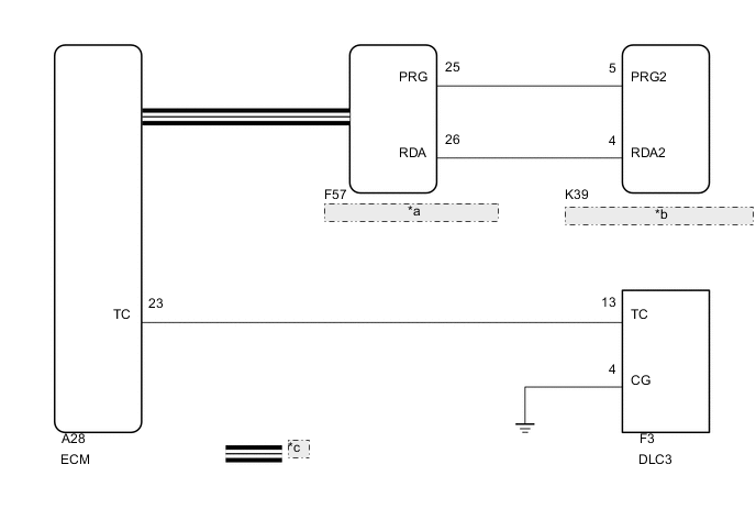
| *a | Main Body ECU (Multiplex Network Body ECU) |
| *b | Tire Pressure Warning ECU and Receiver |
| *c | CAN Communication Line |
PROCEDURE
-
CHECK CAN COMMUNICATION SYSTEM
-
Check if a CAN communication system DTC is output.
-
w/o Toyota Safety Sense Click here
-
w/ Toyota Safety Sense Click here
Result Result Proceed to CAN communication system DTC is not output A CAN communication system DTC is output (w/o Toyota Safety Sense) B CAN communication system DTC is output (w/ Toyota Safety Sense) C -
B 
GO TO CAN COMMUNICATION SYSTEM Click here
C
GO TO CAN COMMUNICATION SYSTEM Click here
A 
-
-
CHECK DTC (C2179/79)
-
Check if DTC C2179/79 is output Click here.
Result Result Proceed to DTC C2179/79 is not output. A DTC C2179/79 is output. B
B
GO TO DTC C2179/79 Click here
A
-
-
CHECK HARNESS AND CONNECTOR (TC of DLC3 - ECM)
-
Disconnect the A28 ECM connector.
-
Measure the resistance according to the value(s) in the table below.
Standard Resistance Tester Connection Condition Specified Condition F3-13 (TC) - A28-57 (TC) Always Below 1 Ω F3-13 (TC) or A28-57 (TC) - Body ground Always 10 kΩ or higher
NG
REPAIR OR REPLACE HARNESS OR CONNECTOR
OK
-
-
CHECK HARNESS AND CONNECTOR (CG of DLC3 - BODY GROUND)
-
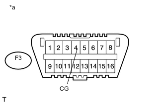
Text in Illustration *a Front view of DLC3 Measure the resistance according to the value(s) in the table below.
Standard Resistance Tester Connection Condition Specified Condition F3-4 (CG) - Body ground Always Below 1 Ω
NG
REPAIR OR REPLACE HARNESS OR CONNECTOR
OK
-
-
INSPECT DLC3 (TC VOLTAGE)
-
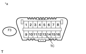
Text in Illustration *a Front view of DLC3 Connect the ECM connector.
-
Measure the voltage according to the value(s) in the table below.
Standard Voltage Tester Connection Switch Condition Specified Condition F3-13 (TC) - F3-4 (CG) Ignition switch ON (IG) 11 to 14 V
OK
REPLACE PROCEED TO NEXT SUSPECTED AREA SHOWN IN PROBLEM SYMPTOMS TABLE Click here
NG
REPLACE ECM Click here
-