REAR AXLE BEAM INSTALLATION

PROCEDURE
-
INSTALL REAR AXLE CARRIER BUSH LH
-
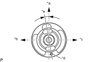
Text in Illustration *a Upper Side *b Front Side *c Rear Side *d Bush Mark *e 7° to 13° Align the matchmarks on a new rear axle carrier bush LH and the rear axle beam assembly and temporarily install the rear axle carrier bush LH to the rear axle beam assembly, as shown in the illustration.
Note
Install the new bush in the same orientation as the old one was prior to removal, because they are directional.
-
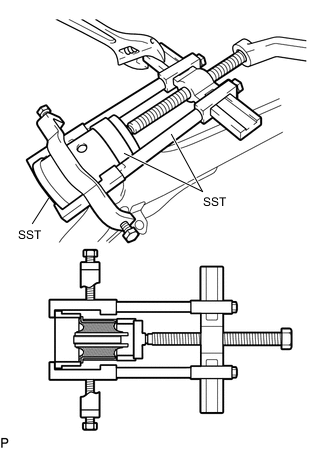
Using SST, install the rear axle carrier bush LH to the rear axle beam assembly.
- SST
- 09223-15020
- 09387-02010
- 09950-40011 ( 09951-04020, 09952-04010, 09953-04030, 09954-04030, 09955-04051, 09957-04010, 09958-04011 )
- 09950-60020 ( 09951-00810 )
Note
Do not damage the rubber portion when installing the rear axle carrier bush LH.
-
-
INSTALL REAR AXLE CARRIER BUSH RH
Tech Tips
Use the same procedure as for the LH side.
-
TEMPORARILY TIGHTEN REAR AXLE BEAM ASSEMBLY
-
Slowly jack up the rear axle beam assembly with an engine lifter using 2 wooden blocks and 2 attachments or equivalent tools and temporarily tighten the rear axle beam assembly to the body with the 2 B bolts.
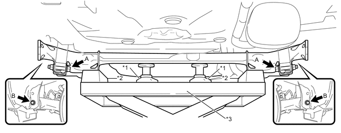
Text in Illustration *1 Attachment *2 Wooden Block *3 Engine Lifter - - Note
Make sure to secure the rear axle beam assembly to prevent it from dropping.
-
Temporarily tighten the rear axle beam assembly to the rear shock absorber assemblies LH and RH with the 2 A bolts and 2 nuts.
Note
Since stopper nuts are used, turn the bolts.
-
-
INSTALL REAR COIL SPRING LH
-
INSTALL REAR COIL SPRING RH
Tech Tips
Use the same procedure as for the LH side.
-
INSTALL REAR AXLE BEAM DYNAMIC DAMPER LH (w/ Dynamic Damper)
-
Install the rear axle beam dynamic damper LH to the rear axle beam assembly with the bolt.
- Torque:
- 50 N*m { 510 kgf*cm, 37 ft.*lbf }
-
-
INSTALL REAR AXLE BEAM DYNAMIC DAMPER RH (w/ Dynamic Damper)
Tech Tips
Use the same procedure as for the LH side.
-
INSTALL REAR AXLE HUB AND BEARING ASSEMBLY LH
-
INSTALL REAR AXLE HUB AND BEARING ASSEMBLY RH
Tech Tips
Use the same procedure as for the LH side.
-
INSPECT REAR AXLE HUB BEARING LOOSENESS
-
INSPECT REAR AXLE HUB RUNOUT
-
INSTALL REAR DISC
-
INSTALL REAR DISC BRAKE CYLINDER ASSEMBLY LH
-
INSTALL REAR DISC BRAKE CYLINDER ASSEMBLY RH
Tech Tips
Use the same procedure as for the LH side.
-
INSTALL NO. 3 PARKING BRAKE CABLE ASSEMBLY
-
Install the No. 3 parking brake cable assembly with the bolt and a new cable clamp.
- Torque:
- 6.0 N*m { 61 kgf*cm, 53 in.*lbf }
-
Install the casing cap to the rear disc brake cylinder guide.
-
Install the No. 3 parking brake cable end to the rear disc brake cylinder operation lever.
-
-
INSTALL NO. 2 PARKING BRAKE CABLE ASSEMBLY
Tech Tips
Use the same procedure as for the No. 3 parking brake cable assembly.
-
INSTALL REAR NO. 4 BRAKE TUBE
-
Install the rear No. 4 brake tube to the rear axle beam assembly with the nut.
- Torque:
- 5.0 N*m { 51 kgf*cm, 48 in.*lbf }
-
Connect the 2 rear flexible hose LH to the rear axle beam assembly with 2 new clips.
-
Using a union nut wrench 10 mm, install the rear No. 4 brake tube while holding the rear flexible hose LH with a wrench.
- Torque:
- 15 N*m { 155 kgf*cm, 11 ft.*lbf }
Note
Use the formula to calculate special torque values for situations where a union nut wrench is combined with a torque wrench Click here.
-
-
INSTALL REAR NO. 3 BRAKE TUBE
Tech Tips
Use the same procedure as for the rear No. 4 brake tube.
-
INSTALL SKID CONTROL SENSOR WIRE LH
-
INSTALL SKID CONTROL SENSOR WIRE RH
Tech Tips
Use the same procedure as for the LH side.
-
INSTALL REAR WHEELS
- Torque:
- 103 N*m { 1050 kgf*cm, 76 ft.*lbf }
-
STABILIZE SUSPENSION
-
Lower the vehicle.
-
Bounce the vehicle up and down several times to stabilize the suspension.
-
-
FULLY TIGHTEN REAR AXLE BEAM ASSEMBLY
-
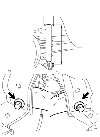
Text in Illustration *a LH Side *b RH Side Suspend the jack on the rear axle spring seat and adjust the length of the rear shock absorber assembly to the reference value.
Length of shock absorber 220 mm (8.66 in.) -
Fully tighten the 2 bolts.
- Torque:
- 90 N*m { 918 kgf*cm, 66 ft.*lbf }
-
-
FULLY TIGHTEN REAR SHOCK ABSORBER ASSEMBLY LH
-
FULLY TIGHTEN REAR SHOCK ABSORBER ASSEMBLY RH
Tech Tips
Use the same procedure as for the LH side.
-
CONNECT CABLE TO NEGATIVE AUXILIARY BATTERY TERMINAL
-
BLEED BRAKE LINE
-
ADJUST PARKING BRAKE LEVER TRAVEL
-
INSPECT REAR WHEEL ALIGNMENT
-
INSPECT SPEED SENSOR SIGNAL