REAR AXLE BEAM REMOVAL

CAUTION / NOTICE / HINT
Note
-
When the brake pedal is first depressed after replacing the brake pads or pushing back the disc brake piston, DTC C1214 may be output. As there is no malfunction, clear the DTC.
-
While the auxiliary battery is connected, even if the ignition switch is off, the brake control system activates when the brake pedal is depressed or the door courtesy switch is turned on. Therefore, even if only brake pads are to be removed and installed, be sure to perform the Disable Brake Control procedure and disconnect the cable from the negative (-) terminal of the auxiliary battery before beginning work.
PROCEDURE
-
PRECAUTION
Note
After turning the ignition switch off, waiting time may be required before disconnecting the cable from the negative (-) auxiliary battery terminal. Therefore, make sure to read the disconnecting the cable from the negative (-) auxiliary battery terminal notice before proceeding with work Click here.
-
DISABLE BRAKE CONTROL
-
REMOVE REAR WHEELS
-
DRAIN BRAKE FLUID
Note
Immediately wash off any brake fluid that comes into contact with any painted surfaces.
-
SEPARATE SKID CONTROL SENSOR WIRE LH
-
SEPARATE SKID CONTROL SENSOR WIRE RH
Tech Tips
Use the same procedure as for the LH side.
-
REMOVE REAR NO. 4 BRAKE TUBE
-
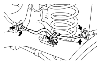
Using a union nut wrench 10 mm, separate the rear No. 4 brake tube while holding the rear flexible hose LH with a wrench.
Note
-
Do not kink or damage the brake line.
-
Do not allow any foreign matter such as dirt and dust to enter the brake line.
-
-
Remove the 2 clips and separate the 2 rear flexible hose LH from the rear axle beam assembly.
-
Remove the nut and the rear No. 4 brake tube.
-
-
REMOVE REAR NO. 3 REAR BRAKE TUBE
Tech Tips
Use the same procedure as for the rear No. 4 brake tube.
-
SEPARATE NO. 3 PARKING BRAKE CABLE ASSEMBLY
-
Separate the No. 3 parking brake cable end from the rear disc brake cylinder operation lever.
-
Using needle-nose pliers, disengage the claws of the casing cap and separate the No. 3 parking brake cable assembly.
-
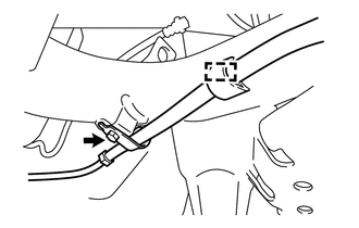
Remove the cable clamp from the rear axle beam assembly.
-
Remove the bolt and separate the No. 3 parking brake cable assembly.
-
Remove the cable clamp from the No. 3 parking brake cable assembly.
Tech Tips
Replace the clamp with a new one when installing the No. 3 parking brake cable assembly.
-
-
SEPARATE NO. 2 PARKING BRAKE CABLE ASSEMBLY
Tech Tips
Use the same procedure as for the No. 3 parking brake cable assembly.
-
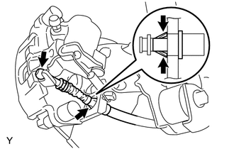
SEPARATE REAR DISC BRAKE CYLINDER ASSEMBLY LH
-
SEPARATE REAR DISC BRAKE CYLINDER ASSEMBLY RH
Tech Tips
Use the same procedure as for the LH side.
-
REMOVE REAR DISC
-
REMOVE REAR AXLE HUB AND BEARING ASSEMBLY LH
-
REMOVE REAR AXLE HUB AND BEARING ASSEMBLY RH
Tech Tips
Use the same procedure as for the LH side.
-
REMOVE REAR AXLE BEAM DYNAMIC DAMPER LH (w/ Dynamic Damper)
-
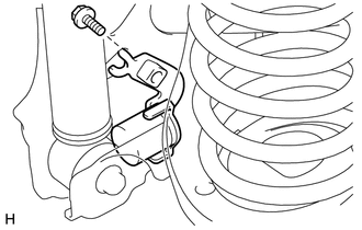
Remove the bolt and the rear axle beam dynamic damper LH from the rear axle beam assembly.
-
-
REMOVE REAR AXLE BEAM DYNAMIC DAMPER RH (w/ Dynamic Damper)
Tech Tips
Use the same procedure as for the LH side.
-
LOOSEN REAR AXLE BEAM ASSEMBLY
-
REMOVE REAR COIL SPRING LH
-
REMOVE REAR COIL SPRING RH
Tech Tips
Use the same procedure as for the LH side.
-
REMOVE REAR AXLE BEAM ASSEMBLY
-
Support the rear axle beam assembly with an engine lifter using 2 wooden blocks and the 2 attachments or equivalent tools as shown in the illustration.
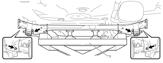
Text in Illustration *1 Attachment *2 Wooden Block *3 Engine Lifter - - Note
Make sure to secure the rear axle beam assembly to prevent it from dropping.
-
Remove the 2 A bolts and 2 nuts while holding the 2 nuts and separate the rear axle beam assembly from the rear shock absorber assemblies LH and RH.
Note
Since stopper nuts are used, turn the bolts.
-
Remove the 2 B bolts and the rear axle beam assembly from the body.
-
-
REMOVE REAR AXLE CARRIER BUSH LH
-
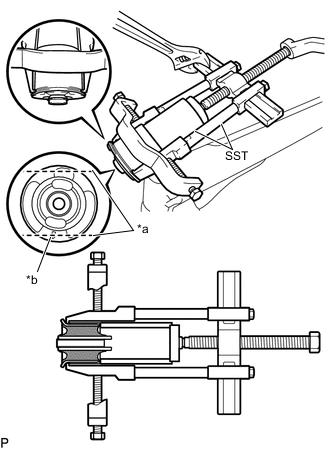
Text in Illustration *a Bend Portions *b Bush Mark Place a matchmark on the rear axle beam assembly with it aligned with the bush mark.
-
Using a chisel and hammer, bend the 2 portions of the bush rib.
Note
Bend the bush rib until the claw of SST can be suspended.
-
Using SST, remove the rear axle carrier bush LH from the rear axle beam assembly.
- SST
- 09612-30012
- 09950-40011 ( 09951-04020, 09952-04010, 09953-04030, 09954-04020, 09955-04011, 09957-04010, 09958-04011 )
- 09950-60010 ( 09951-00590 )
Note
Apply paint to any scratches on the rear axle beam assembly.
-
-
REMOVE REAR AXLE CARRIER BUSH RH
Tech Tips
Use the same procedure as for the LH side.