REAR WHEEL ALIGNMENT INSPECTION
CAUTION / NOTICE / HINT
Note
If the wheel alignment has been adjusted, or if suspension or underbody components have been removed/installed or replaced, be sure to perform the following initialization procedure in order for the system to function normally:
-
Perform zero point calibration of the yaw rate and acceleration sensor.
PROCEDURE
-
INSPECT TIRES
-
MEASURE VEHICLE HEIGHT
-
INSPECT CAMBER
-
Set the camber-caster-kingpin gauge and position the rear wheel on the alignment tester.
-
Inspect the camber.
Camber (Unloaded Vehicle) Camber Right-left Difference -0°57' +/- 30'
(-0.95° +/- 0.5°)
0°30'
(0.5°)
Note
The tolerance for the difference between the left and right wheels is 30' (0.5°) or less for both cambers. If the camber is not within the specified range, inspect the suspension parts and replace them if necessary.
-
-
INSPECT TOE-IN
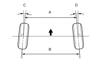
Text in Illustration 
Front of the Vehicle Toe-in (Unloaded Vehicle) Tire Size Specified Condition Right-left Difference 175/65 R15 C + D: 0°22' +/- 15' ( 0.37° +/- 0.25°) 0°30'
(0.5°)
B - A: 3.9 +/- 3.0 mm
(0.154 +/- 0.118 in.)
6.0 mm (0.236 in.) or less 185/60 R15 C + D: 0°20' +/- 15' ( 0.33° +/- 0.25°) 0°30'
(0.5°)
B - A: 3.6 +/- 3.0 mm
(0.142 +/- 0.118 in.)
6.0 mm (0.236 in.) or less 195/50 R16 C + D: 0°22' +/- 15' ( 0.37° +/- 0.25°) 0°30'
(0.5°)
B - A: 3.9 +/- 3.0 mm
(0.154 +/- 0.118 in.)
6.0 mm (0.236 in.) or less Tech Tips
-
Measure "B - A" only when "C + D" cannot be measured.
-
If the toe-in is not within the specified range, inspect the suspension parts and replace them if necessary.
-
-
PLACE FRONT WHEELS FACING STRAIGHT AHEAD
-
PERFORM YAW RATE AND ACCELERATION SENSOR CALIBRATION