FRONT AXLE HUB INSTALLATION

CAUTION / NOTICE / HINT
Tech Tips
-
Use the same procedure for the RH side and LH side.
-
The procedure listed below is for the LH side.
PROCEDURE
-
INSTALL FRONT AXLE HUB BEARING
-
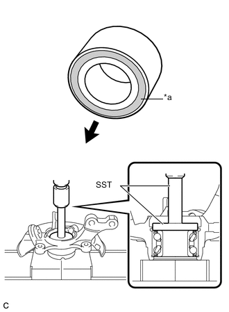
Text in Illustration *a Magnetic Rotor Side 
Inside of the vehicle Using SST and a press, insert a new front axle hub bearing, with its magnetic rotor side facing the inside of the vehicle, until it reaches the end of the steering knuckle.
- SST
- 09950-60020 ( 09951-00710 )
- 09950-70010 ( 09951-07100 )
Note
-
Do not remove the inner race because the front axle hub bearing is built into the oil seal.
-
Do not use bearings that have been removed.
-
Do not wipe off any grease that has been applied to new bearings.
-
Do not bring magnets close to the magnetic rotor surface of the bearing.
-
Keep the magnetic rotor surface of the bearing free of foreign matter.
-
-
INSTALL FRONT AXLE HUB SUB-ASSEMBLY
-
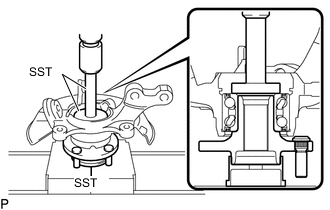
Using SST and a press, press the front axle hub sub-assembly into the steering knuckle.
- SST
- 09608-32010
- 09950-60010 ( 09951-00580 )
- 09950-70010 ( 09951-07100 )
-
-
INSTALL FRONT AXLE HUB HOLE SNAP RING
-
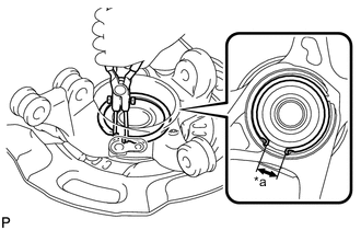
Text in Illustration *a Speed Sensor Installation Gap Using snap ring pliers, install a new front axle hub hole snap ring, as shown in the illustration.
Note
-
Do not overlap the end of the front axle hub hole snap ring and the installation hole in the speed sensor on the knuckle side.
-
Do not damage the magnetic rotor surface of the bearing when installing the front axle hub hole snap ring.
-
-
-
INSTALL FRONT AXLE ASSEMBLY
-
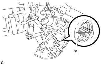
Text in Illustration *a Matchmark Align the matchmarks on the front drive shaft assembly and front axle hub assembly, and install the front drive shaft assembly to the front axle hub assembly.
Note
-
Do not damage the lower ball joint.
-
Do not damage the threads of the drive shaft.
-
Do not damage the speed sensor rotor.
-
Do not damage the drive shaft outboard joint boot.
-
-
Install the front axle assembly to the front shock absorber with the 2 bolts and 2 nuts.
- Torque:
- 164 N*m { 1672 kgf*cm, 121 ft.*lbf }
Tech Tips
Keep the bolt from rotating while turning the nut.
-
-
INSTALL FRONT LOWER SUSPENSION ARM
-
Install the front lower suspension arm to the steering knuckle with a new castle nut.
- Torque:
- 98 N*m { 999 kgf*cm, 72 ft.*lbf }
Note
If the holes for the clip are not aligned, tighten the nut by a further turn of up to 60°.
-
Install a new clip.
-
-
INSTALL TIE ROD END SUB-ASSEMBLY
-
Install the tie rod end sub-assembly to the steering knuckle with a new castle nut.
- Torque:
- 49 N*m { 500 kgf*cm, 36 ft.*lbf }
Note
If the holes for the clip are not aligned, tighten the nut by a further turn of up to 60°.
-
Install a new cotter pin.
-
-
INSTALL FRONT STABILIZER LINK ASSEMBLY
-
INSTALL FRONT DISC
-
INSTALL FRONT DISC BRAKE CYLINDER ASSEMBLY
-
TEMPORARILY INSTALL FRONT AXLE SHAFT NUT
-
Clean the threaded parts on the front drive shaft assembly and a new front axle shaft nut using a non-residue solvent.
Note
-
Be sure to perform this work even when using a new drive shaft.
-
Keep the threaded parts free of oil and foreign matter.
-
-
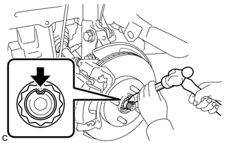
Using a socket wrench 30 mm, while applying the brakes, temporarily install the front axle shaft nut.
- Torque:
- 216 N*m { 2203 kgf*cm, 159 ft.*lbf }
Note
Stake the front axle shaft nut after inspecting for looseness and runout in the following steps.
Tech Tips
Keep depressing the brake pedal to prevent the drive shaft from rotating.
-
-
SEPARATE FRONT DISC BRAKE CYLINDER ASSEMBLY
-
REMOVE FRONT DISC
-
INSPECT FRONT AXLE HUB BEARING LOOSENESS
-
INSPECT FRONT AXLE HUB RUNOUT
-
INSTALL FRONT DISC
-
INSTALL FRONT DISC BRAKE CYLINDER ASSEMBLY
-
INSTALL FRONT SPEED SENSOR
-
Install the front speed sensor to the steering knuckle with the bolt.
- Torque:
- 8.5 N*m { 87 kgf*cm, 75 in.*lbf }
Note
-
Check that the front speed sensor tip and installation portion are free of foreign matter.
-
Install the front speed sensor without turning it from its original installation angle.
-
Install the front speed sensor and the front flexible hose with the bolt.
- Torque:
- 29 N*m { 300 kgf*cm, 22 ft.*lbf }
Note
Install the front speed sensor and front flexible hose without twisting them.
-
-
INSTALL FRONT AXLE SHAFT NUT
-
Using a chisel and hammer, stake the front axle shaft nut.
-
-
INSTALL FRONT WHEEL
- Torque:
- 103 N*m { 1050 kgf*cm, 76 ft.*lbf }
-
CONNECT CABLE TO NEGATIVE AUXILIARY BATTERY TERMINAL
-
INSPECT AND ADJUST FRONT WHEEL ALIGNMENT
-
INSPECT SPEED SENSOR SIGNAL