FRONT AXLE HUB REMOVAL

CAUTION / NOTICE / HINT
Note
-
When the brake pedal is first depressed after replacing the brake pads or pushing back the disc brake piston, DTC C1214 may be output. As there is no malfunction, clear the DTC.
-
While the auxiliary battery is connected, even if the ignition switch is off, the brake control system activates when the brake pedal is depressed or the door courtesy switch is turned on. Therefore, even if only brake pads are to be removed and installed, be sure to perform the Disable Brake Control procedure and disconnect the cable from the negative (-) terminal of the auxiliary battery before beginning work.
Tech Tips
-
Use the same procedure for the RH side and LH side.
-
The procedure listed below is for the LH side.
PROCEDURE
-
PRECAUTION
Note
After turning the ignition switch off, waiting time may be required before disconnecting the cable from the negative (-) auxiliary battery terminal. Therefore, make sure to read the disconnecting the cable from the negative (-) auxiliary battery terminal notice before proceeding with work Click here.
-
DISABLE BRAKE CONTROL
-
REMOVE FRONT WHEEL
-
REMOVE FRONT AXLE SHAFT NUT
-
SEPARATE FRONT SPEED SENSOR
-
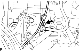
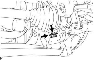
Remove the bolt and separate the front speed sensor wire and the front flexible hose from the front shock absorber assembly.
-
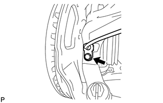
Remove the bolt and separate the front speed sensor from the front axle assembly.
Note
-
Keep the front speed sensor tip and installation portion free of foreign matter.
-
Remove the front speed sensor without turning it from its original installation angle.
-
-
-
SEPARATE FRONT DISC BRAKE CYLINDER ASSEMBLY
-
REMOVE FRONT DISC
-
SEPARATE TIE ROD END SUB-ASSEMBLY
-
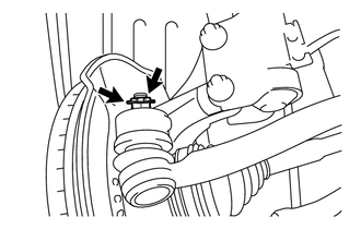
Remove the cotter pin and castle nut.
-
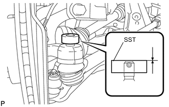
Install SST to the threaded section of the tie rod end.
- SST
- 09960-20010 ( 09961-02060 )
Note
Make sure the upper ends of the threaded section of the tie rod end and SST are aligned.
-
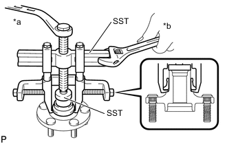
Using SST, separate the tie rod end from the front axle assembly.
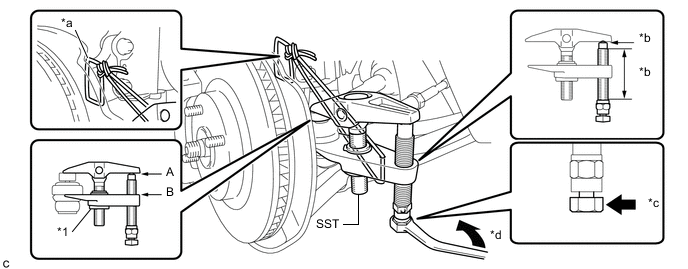
Text in Illustration *1 Center Nut - - *a String *b Molybdenum Grease Application Area *c Place the wrench here *d Turn - SST
- 09960-20010 ( 09961-02010 )
Note
-
Apply molybdenum grease to the bolt threads and the tip of SST.
-
Make sure to tie the string of SST to the vehicle to prevent SST from dropping.
-
Install SST so that A and B are parallel.
-
Be sure to place the wrench on the part indicated in the illustration.
-
Do not damage the ball joint dust cover.
-
Do not damage the front disc brake dust cover.
-
-
SEPARATE FRONT LOWER SUSPENSION ARM
-
Remove the clip and castle nut.
-
Install SST to the threaded section of the lower ball joint.
- SST
- 09960-20010 ( 09961-02060 )
Note
Make sure the upper ends of the threaded section of the lower ball joint and SST are aligned.
-
Using SST, separate the front lower suspension arm from the front axle assembly.
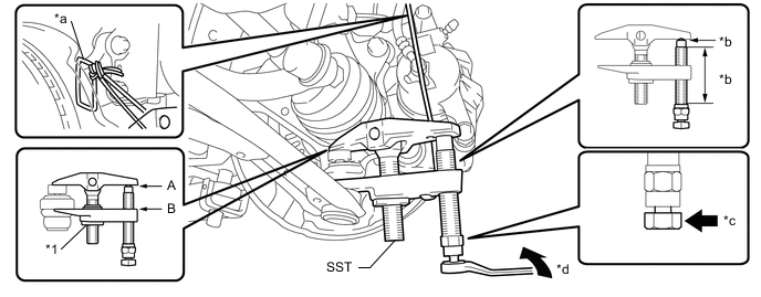
Text in Illustration *1 Center Nut - - *a String *b Molybdenum Grease Application Area *c Place the wrench here *d Turn - SST
- 09960-20010 ( 09961-02010 )
Note
-
Apply molybdenum grease to the bolt threads and the tip of SST.
-
Make sure to tie the string of SST to the vehicle to prevent SST from dropping.
-
Install SST so that A and B are parallel.
-
Be sure to place the wrench on the part indicated in the illustration.
-
Do not damage the lower ball joint dust cover.
-
Do not damage the drive shaft outboard joint boots.
-
Do not damage the front disc brake dust cover.
-
-
SEPARATE FRONT STABILIZER LINK ASSEMBLY
-
REMOVE FRONT AXLE ASSEMBLY
-
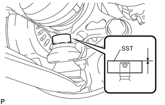
Text in Illustration *a Matchmark Put matchmarks on the front drive shaft assembly and front axle assembly.
-
Using a plastic hammer, tap the end of the drive shaft assembly and separate the fitting between the drive shaft assembly and the front axle assembly.
Note
Do not hammer the threads of the drive shaft assembly.
Tech Tips
If it is difficult to separate the fitting, tap the end of the drive shaft assembly with a brass bar and hammer.
-
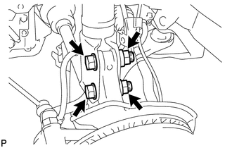
Remove the 2 nuts, 2 bolts and the front axle assembly.
Note
-
Do not damage the lower ball joint.
-
Do not damage the threads of the drive shaft.
-
Do not damage the speed sensor rotor.
-
Do not damage the drive shaft outboard joint boot.
-
Suspend the drive shaft with a piece of string or equivalent.
Tech Tips
Keep the bolt from rotating while turning the nut.
-
-
-
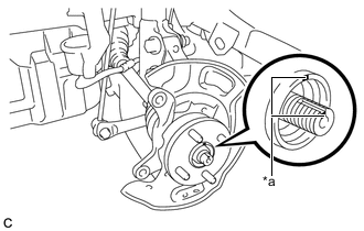
REMOVE FRONT AXLE HUB HOLE SNAP RING
-
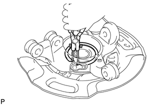
Using snap ring pliers, remove the front axle hub hole snap ring.
Note
When removing the front axle hub hole snap ring, do not damage the magnetic rotor surface.
-
-
REMOVE FRONT AXLE HUB SUB-ASSEMBLY
-
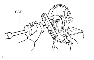
Fix the steering knuckle in a vise between aluminum plates.
Note
Do not overtighten the vise.
-
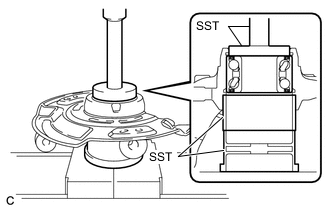
Using SST, remove the front axle hub sub-assembly.
- SST
- 09520-00031
-
Text in Illustration *a Turn *b Hold Using SST, remove the axle hub bearing inner race.
- SST
- 09950-40011 ( 09951-04020, 09952-04010, 09953-04020, 09954-04010, 09955-04011, 09957-04010, 09958-04011 )
- 09950-60010 ( 09951-00370 )
Note
-
When removing the inner race, it the axle hub is damaged, replace the axle hub with a new one.
-
Apply a small amount of grease to the threads and tip of SST before use.
-
-
REMOVE FRONT AXLE HUB BEARING
-
Install the removed axle hub bearing inner race to the outer side of the front axle hub bearing.
-
Using SST and a press, remove the front axle hub bearing.
- SST
- 09223-15020
- 09387-02010
- 09950-60010 ( 09951-00630 )
- 09950-70010 ( 09951-07100 )
-