FRONT AXLE HUB BOLT REPLACEMENT

CAUTION / NOTICE / HINT
Note
-
When the brake pedal is first depressed after replacing the brake pads or pushing back the disc brake piston, DTC C1214 may be output. As there is no malfunction, clear the DTC.
-
While the auxiliary battery is connected, even if the ignition switch is off, the brake control system activates when the brake pedal is depressed or the door courtesy switch is turned on. Therefore, even if only brake pads are to be removed and installed, be sure to perform the Disable Brake Control procedure and disconnect the cable from the negative (-) terminal of the auxiliary battery before beginning work.
Tech Tips
-
Use the same procedure for the RH side and LH side.
-
The procedure listed below is for the LH side.
PROCEDURE
-
PRECAUTION
Note
After turning the ignition switch off, waiting time may be required before disconnecting the cable from the negative (-) auxiliary battery terminal. Therefore, make sure to read the disconnecting the cable from the negative (-) auxiliary battery terminal notice before proceeding with work Click here.
-
DISABLE BRAKE CONTROL
-
REMOVE FRONT WHEEL
-
SEPARATE FRONT DISC BRAKE CYLINDER ASSEMBLY
-
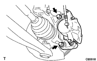
Remove the 2 bolts and separate the front disc brake cylinder assembly.
Note
Hang the front disc brake cylinder assembly using a piece of string or the equivalent.
-
-
REMOVE FRONT DISC
-
REMOVE FRONT AXLE HUB BOLT
-
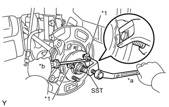
Text in Illustration *1 Service Nut *a Turn *b Hold Temporarily install 2 service nuts to the 2 front axle hub bolts as shown in the illustration.
Recommended Service Nut Thread Diameter Thread Pitch 12.0 mm (0.472 in.) 1.5 mm (0.0591 in.) Note
Install the service nuts to prevent damage to the front axle hub bolts.
-
Using SST and a screwdriver or the equivalent to hold the front axle hub sub-assembly, remove the front axle hub bolt.
- SST
- 09628-10011
Note
Do not damage the threads of the front axle hub bolts.
-
-
INSTALL FRONT AXLE HUB BOLT
-
Temporarily install a new front axle hub bolt to the front axle hub sub-assembly.
-
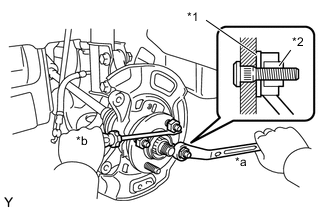
Text in Illustration *1 Washer *2 Service Nut *a Turn *b Hold Install the washer and the service nut to the front axle hub bolt, as shown in the illustration.
Recommended Service Nut Thread Diameter Thread Pitch 12.0 mm (0.472 in.) 1.5 mm (0.0591 in.) -
Using a screwdriver or the equivalent to hold the front axle hub sub-assembly, install the front axle hub bolt by tightening the service nut.
Note
-
Install the service nuts to prevent damage to the front axle hub bolts.
-
Do not damage the threads of the front axle hub bolts.
-
-
Remove the 3 service nuts and washer from the 3 front axle hub bolts.
-
-
INSTALL FRONT DISC
-
INSTALL FRONT DISC BRAKE CYLINDER ASSEMBLY
-
Install the front disc brake cylinder assembly to the steering knuckle with the 2 bolts.
- Torque:
- 107 N*m { 1089 kgf*cm, 79 ft.*lbf }
-
-
INSTALL FRONT WHEEL
- Torque:
- 103 N*m { 1050 kgf*cm, 76 ft.*lbf }
-
CONNECT CABLE TO NEGATIVE AUXILIARY BATTERY TERMINAL