FRONT DRIVE SHAFT ASSEMBLY REASSEMBLY

PROCEDURE
-
INSTALL FRONT DRIVE SHAFT DUST COVER
-
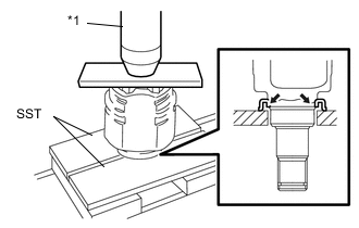
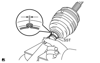
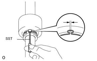
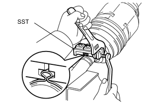
Text in Illustration *1 Press Using SST and a press, install a new front drive shaft dust cover into the front drive inboard joint assembly until it is flush with the end.
- SST
- 09527-10011
Note
-
Install the dust cover in the correct orientation.
-
Do not deform the dust cover.
-
-
INSTALL FRONT DRIVE SHAFT HOLE SNAP RING
-
Install a new front drive shaft hole snap ring.
-
-
INSTALL FRONT AXLE OUTBOARD JOINT BOOT
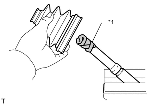
Text in Illustration *1 Protective Tape
-
Wrap the spline of the outboard joint shaft assembly with protective tape.
-
Install new parts onto the outboard joint shaft assembly in the following order.
-
Front No. 2 axle outboard joint boot clamp
-
Front axle outboard joint boot
-
Front axle outboard joint boot clamp
-
-
Pack the joint portion of the outboard joint shaft assembly and the front axle outboard joint boot with grease.
Standard Grease Capacity 151 to 161 g (5.4 to 5.6 oz.) -
Install the front axle outboard joint boot into the grooves of the outboard joint shaft assembly.
Note
Keep the groove free of grease.
-
-
INSTALL FRONT NO. 2 AXLE OUTBOARD JOINT BOOT CLAMP
-
Hold the outboard joint shaft assembly in a vise between aluminum plates.
Note
Do not overtighten the vise.
-
Install a new front No. 2 axle outboard joint boot clamp to the front axle outboard joint boot.
-
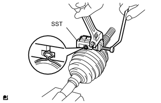
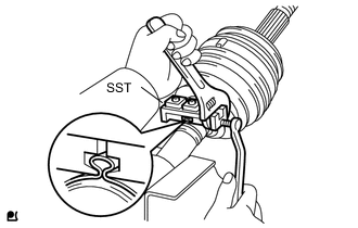
Place SST onto the front No. 2 axle outboard joint boot clamp.
- SST
- 09521-24010
-
Tighten SST so that the front No. 2 axle outboard joint boot clamp is pinched.
Note
Do not overtighten SST.
-
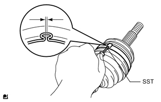
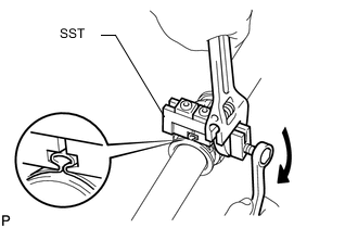
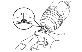
Using SST, adjust the clearance of the front No. 2 axle outboard joint boot clamp.
- SST
- 09240-00020
Standard Clearance 0.8 mm (0.0315 in.) or less Note
If the measured value exceeds the specified value, retighten the boot clamp.
-
-
INSTALL FRONT AXLE OUTBOARD JOINT BOOT CLAMP
-
Hold the outboard joint shaft assembly in a vise between aluminum plates.
Note
Do not overtighten the vise.
-
Install a new front axle outboard joint boot clamp to the front axle outboard joint boot.
-
Place SST onto the front axle outboard joint boot clamp.
- SST
- 09521-24010
-
Tighten SST so that the front axle outboard joint boot clamp is pinched.
Note
Do not overtighten SST.
-
Using SST, adjust the clearance of the front axle outboard joint boot clamp.
- SST
- 09240-00020
Standard Clearance 0.8 mm (0.0315 in.) or less Note
If the measured value exceeds the specified value, retighten the boot clamp.
-
-
INSTALL FRONT DRIVE SHAFT DAMPER (for RH Side)
-
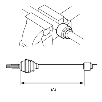
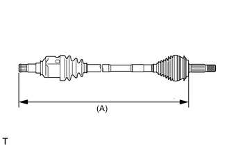
Install the front drive shaft damper RH onto dimension (A) shown in the illustration.
Dimension (A) 425.6 to 429.6 mm (1.396 to 1.409 ft.) Note
Install the damper in the correct orientation.
-
-
INSTALL FRONT DRIVE SHAFT DAMPER CLAMP RH (for RH Side)
-
Hold the outboard joint shaft assembly in a vise between aluminum plates.
Note
Do not overtighten the vise.
-
Install a new front drive shaft damper clamp RH to the front drive shaft damper.
Note
Be sure to install the drive shaft damper clamp on the inboard joint side in the correct position.
-
Place SST onto the front drive shaft damper clamp RH.
- SST
- 09521-24010
-
Tighten SST so that the front drive shaft damper clamp RH is pinched.
Note
Do not overtighten SST.
-
Using SST, adjust the clearance of the front drive shaft damper clamp RH.
- SST
- 09240-00020
Standard Clearance 0.8 mm (0.0315 in.) or less Note
If the measured value exceeds the specified value, retighten the drive shaft damper clamp.
-
-
INSTALL FRONT DRIVE INBOARD JOINT ASSEMBLY
-
Install new parts onto the outboard joint shaft assembly in the following order.
-
Front axle inboard joint boot clamp
-
Front axle inboard joint boot
-
Front No. 2 axle inboard joint boot clamp
-
-
Fix the outboard joint shaft assembly in a vise between aluminum plates.
Note
Do not overtighten the vise.
-
Remove the protective tape.
-
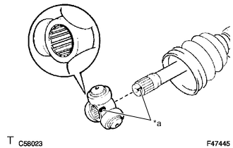
Text in Illustration *a Matchmark Align the matchmarks and install the tripod joint assembly onto the outboard joint shaft assembly.
Note
Face the serrated side of the tripod joint outward and install it onto the outboard joint end.
-
Using a brass bar and hammer, install the tripod joint assembly.
Note
-
Do not hit the rollers.
-
Keep the tripod joint free of foreign matter.
-
-
Using a snap ring expander, install a new snap ring.
-
Pack the front drive inboard joint assembly with grease.
Standard Grease Capacity 125 to 135 g (4.4 to 4.7 oz.) -
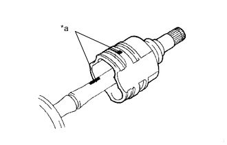
Text in Illustration *a Matchmark Align the matchmarks and install the front drive inboard joint assembly onto the outboard joint shaft assembly.
-
Install the front axle inboard joint boot into the grooves of the front drive inboard joint assembly and the outboard joint shaft assembly.
Note
Keep the grooves free of grease.
-
-
INSTALL FRONT AXLE INBOARD JOINT BOOT CLAMP
-
Hold the outboard joint shaft assembly in a vise between aluminum plates.
Note
Do not overtighten the vise.
-
Install a new front axle inboard joint boot clamp to the front axle inboard joint boot.
-
Place SST onto the front axle inboard joint boot clamp.
- SST
- 09521-24010
-
Tighten SST so that the front axle inboard joint boot clamp is pinched.
Note
Do not overtighten SST.
-
Using SST, adjust the clearance of the front axle inboard joint boot clamp.
- SST
- 09240-00020
Standard Clearance 0.8 mm (0.0315 in.) or less Note
If the measured value exceeds the specified value, retighten the boot clamp.
-
-
INSTALL FRONT NO. 2 AXLE INBOARD JOINT BOOT CLAMP
-
Install a new front No. 2 axle inboard joint boot clamp onto the front axle inboard joint boot.
-
Adjust dimension (A) until the drive shaft is within the specified length.
Dimension (A) LH RH 561.9 mm
(1.84 ft.)
845.9 mm
(2.77 ft.)
-
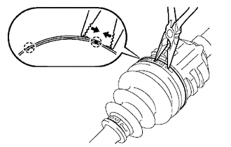
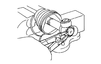
Using needle-nose pliers, engage the 2 claws and install the front No. 2 axle inboard joint boot clamp as shown in the illustration.
Note
-
Do not damage the boot.
-
Do not deform the claw of the hook.
-
-
-
INSPECT FRONT DRIVE SHAFT ASSEMBLY