FRONT DRIVE SHAFT ASSEMBLY REMOVAL

PROCEDURE
-
REMOVE ENGINE UNDER COVER LH
-
REMOVE ENGINE UNDER COVER RH
-
DRAIN HYBRID TRANSAXLE FLUID
-
REMOVE FRONT WHEEL
-
REMOVE FRONT AXLE SHAFT NUT LH
-
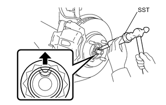
Using SST and a hammer, release the staked part of the front axle shaft nut LH.
- SST
- 09930-00010
Note
-
Insert SST into the groove with the flat surface facing up.
-
Do not damage the tip of SST using grinders.
-
Completely unstake the staked part before removing the front axle shaft nut.
-
Do not damage the threads of the front drive shaft.
-
Using a deep socket wrench 30 mm, remove the front axle shaft nut LH.
-
-
REMOVE FRONT AXLE SHAFT NUT RH
Tech Tips
Use the same procedure for the RH side as for the LH side.
-
SEPARATE FRONT SPEED SENSOR LH
-
SEPARATE FRONT SPEED SENSOR RH
Tech Tips
Use the same procedure for the RH side as for the LH side.
-
SEPARATE FRONT STABILIZER LINK ASSEMBLY LH
-
SEPARATE FRONT STABILIZER LINK ASSEMBLY RH
Tech Tips
Use the same procedure for the RH side as for the LH side.
-
SEPARATE TIE ROD END SUB-ASSEMBLY LH
-
SEPARATE TIE ROD END SUB-ASSEMBLY RH
Tech Tips
Use the same procedure for the RH side as for the LH side.
-
SEPARATE FRONT LOWER SUSPENSION ARM SUB-ASSEMBLY LH
-
SEPARATE FRONT LOWER SUSPENSION ARM SUB-ASSEMBLY RH
Tech Tips
Use the same procedure for the RH side as for the LH side.
-
SEPARATE FRONT AXLE ASSEMBLY LH
-
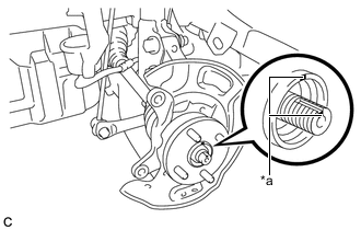
Text in Illustration *a Matchmark Place matchmarks on the front drive shaft assembly LH and the front axle hub sub-assembly.
-
Using a plastic hammer, tap the end of the front drive shaft assembly LH and disengage the fitting between the front drive shaft assembly LH and the front axle assembly LH.
Tech Tips
If it is difficult to disengage the fitting, tap the end of the drive shaft with a brass bar and hammer.
-
Push the front axle assembly LH out of the vehicle to remove the front drive shaft assembly LH from the front axle assembly LH.
Note
-
Do not push the front axle further out of the vehicle than is necessary.
-
Do not damage the outboard joint boot.
-
Do not damage the speed sensor rotor.
-
Suspend the drive shaft with a piece of string or the equivalent.
-
-
-
SEPARATE FRONT AXLE ASSEMBLY RH
Tech Tips
Use the same procedure for the RH side as for the LH side.
-
REMOVE FRONT DRIVE SHAFT ASSEMBLY LH
-
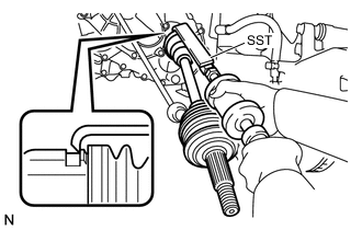
Using SST, remove the front drive shaft assembly LH as shown in the illustration.
- SST
- 09520-01010
- 09520-24010 ( 09520-32040 )
Note
-
Do not damage the oil seal.
-
Do not damage the inboard joint boot.
-
Do not drop the drive shaft.
-
-
REMOVE FRONT DRIVE SHAFT ASSEMBLY RH
-
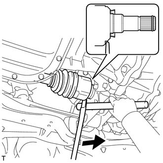
Using a tire lever and brass bar, remove the front drive shaft assembly RH.
Note
-
Do not damage the oil seal.
-
Do not damage the inboard joint boot.
-
Do not drop the drive shaft.
-
-
-
FIX FRONT AXLE ASSEMBLY
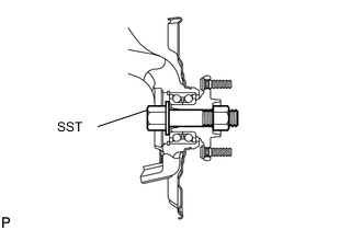
- SST
- 09608-16042 ( 09608-02021, 09608-02041 )
Tech Tips
The hub bearing could be damaged if it is subjected to the vehicle is full weight, such as when moving the vehicle with the drive shaft removed. If it is absolutely necessary to place the vehicle is full weight on the hub bearing, first support it with SST.