SHIFT LEVER POSITION SENSOR INSTALLATION

PROCEDURE
-
INSTALL SHIFT LEVER POSITION SENSOR
-
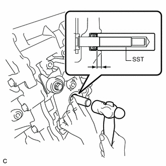
Using SST and a hammer, tap in a new parking lock shaft oil seal to the hybrid vehicle transaxle assembly.
- SST
- 09350-30020 ( 09350-07110 )
Oil seal installation depth 5.5 to 6.4 mm (0.217 to 0.251 in.) Note
It is not always necessary to replace or remove/install the parking lock shaft oil seal at the same time when replacing the shift lever position sensor.
Tech Tips
Remove/install the parking lock shaft oil seal only if oil leaks from the parking lock shaft oil seal or other faults are found when the shift lever position sensor is removed.
-
Install the shift lever position sensor to the hybrid vehicle transaxle assembly.
Note
-
Do not reuse the shift lever position sensor if it has been dropped or subjected to a severe impact.
-
Do not allow moisture to adhere to the connector terminal.
-
-
Temporarily install the 2 bolts.
-
Install the lock plate and tighten the lock nut.
- Torque:
- 6.9 N*m { 70 kgf*cm, 61 in.*lbf }
-
Temporarily install the transmission control shaft lever to the shift lever position sensor.
-
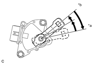
Text in Illustration *a P Position *b N Position Rotate the transmission control shaft lever clockwise until it stops, and then from that position rotate it counterclockwise by 2 notches to set it to the N position.
-
Remove the transmission control shaft lever from the shift lever position sensor.
-
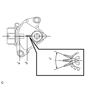
Text in Illustration *a Neutral Basic Line *b Protruding Part *c Range of Play Align the protruding part with the neutral basic line.
Note
There is play on the nut stopper side (protruding part). Align the center point of the range of the play with the neutral basic line.
-
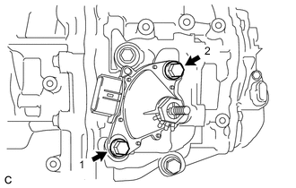
Tighten the 2 bolts in the order shown in the illustration.
- Torque:
- 13 N*m { 133 kgf*cm, 10 ft.*lbf }
-
Using a screwdriver, secure the lock nut with the lock plate.
-
Install the transmission control shaft lever to the shift lever position sensor with the washer and nut.
- Torque:
- 13 N*m { 130 kgf*cm, 9 ft.*lbf }
-
Connect the connector to the shift lever position sensor.
-
-
INSTALL TRANSMISSION CONTROL CABLE ASSEMBLY
-
Install the transmission control cable assembly to the transmission control cable bracket with a new clip.
-
Connect the transmission control cable assembly to the transmission control shaft lever with the nut.
- Torque:
- 12 N*m { 122 kgf*cm, 9 ft.*lbf }
Note
To prevent damage to the transmission control cable assembly and the shift lever assembly, connect the transaxle side of the transmission control cable assembly before connecting the shift lever side.
-
-
CONNECT TRANSMISSION CONTROL CABLE ASSEMBLY
-
INSPECT SHIFT LEVER POSITION
-
ADJUST SHIFT LEVER POSITION
-
INSPECT SHIFT LEVER POSITION SENSOR POSITION
-
ADJUST SHIFT LEVER POSITION SENSOR POSITION
-
INSTALL REAR CONSOLE BOX ASSEMBLY
-
INSTALL ENGINE UNDER COVER LH