SHIFT LEVER INSTALLATION
PROCEDURE
-
INSTALL SHIFT LEVER ASSEMBLY
-
Engage the 3 clamps and install the wire harness to the shift lever assembly.
-
Connect the 2 connectors to the shift lever assembly.
-
Temporarily install the shift lever assembly with the 4 bolts.
-
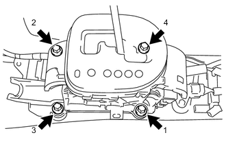
Fully tighten the 4 bolts in the order shown in the illustration.
- Torque:
- 12 N*m { 122 kgf*cm, 9 ft.*lbf }
-
-
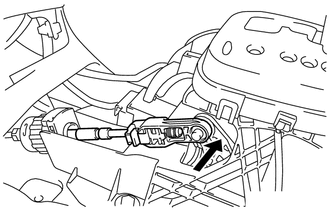
CONNECT TRANSMISSION CONTROL CABLE ASSEMBLY
-
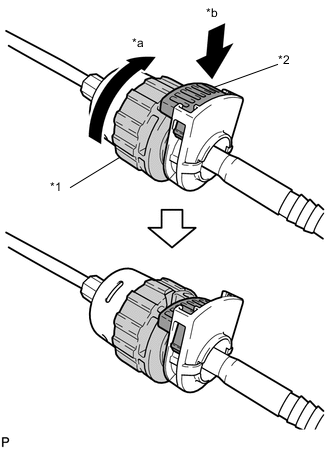
Text in Illustration *1 Nut *2 Lock *a Rotate approximately 180° *b Push in Rotate the nut of the transmission control cable approximately 180° in the direction shown in the illustration, and while holding the nut, push in the lock.
Note
Rotating the nut too much will damage the internal spring, and the transmission control cable assembly will not be reusable. Do not turn the nut too far.
-
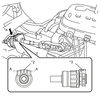
Text in Illustration *1 Shift Lever Plate *2 Projecting Part *3 Lock *a Push in Install the transmission control cable assembly to the shift lever plate.
Note
-
Install the cable outer with the projecting part facing upwards.
-
After installation, make sure that the cable outer lock is projecting from A as shown in the illustration.
-
Make sure that the transmission control cable assembly is securely locked.
Tech Tips
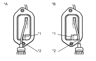
As shown in the illustration, the transmission control cable for LHD models passes along the left side of the projection, while the transmission control cable for RHD models passes along the right side of the projection.
-
-
Text in Illustration *A for LHD *B for RHD *1 Projection *2 Transmission Control Cable Confirm that the shift lever is in N, and then connect the cable end to the shift lever assembly.
Note
-
Securely install the cable end to the shift lever assembly.
-
Install the cable end so that its adjustment lock section is on the driver side.
-
-
-
ADJUST SHIFT LEVER POSITION
-
INSTALL REAR CONSOLE BOX
-
INSTALL SHIFT LEVER KNOB SUB-ASSEMBLY
-
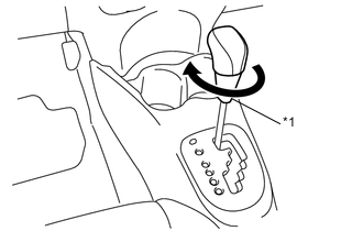
Text in Illustration *1 Shift Lever Knob Cover Turn the shift lever knob sub-assembly clockwise and install the shift lever knob sub-assembly to the shift lever assembly.
Note
Do not hold the shift lever knob cover when tightening the shift lever knob sub-assembly.
-
-
INSPECT SHIFT LEVER POSITION