TRANSMISSION CONTROL CABLE INSTALLATION
PROCEDURE
-
INSTALL NO. 3 TRANSMISSION CONTROL CABLE CLAMP
Tech Tips
Perform this procedure only when replacement of the No. 3 transmission control cable clamp is necessary.
-
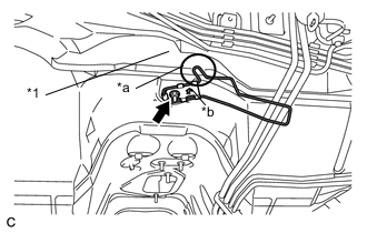
Text in Illustration *1 Dash Silencer *a Pushing against the dash silencer *b Arrow Install the No. 3 transmission control cable clamp to the body with the nut.
- Torque:
- 5.0 N*m { 51 kgf*cm, 44 in.*lbf }
Note
-
Install the No. 3 transmission control cable clamp so that its arrow mark points to the front of the vehicle.
-
Make sure that the detent of the No. 3 transmission control cable clamp is pushing against the dash silencer.
-
-
INSTALL TRANSMISSION CONTROL CABLE ASSEMBLY
-
Pass the transmission control cable into the vehicle and install the transmission control cable assembly to the body with the 4 nuts.
- Torque:
- 5.0 N*m { 51 kgf*cm, 44 in.*lbf }
-
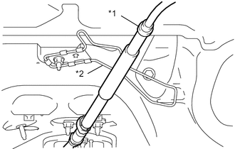
Text in Illustration *1 Transmission Control Cable Assembly *2 No. 3 Transmission Control Cable Clamp Pass the transmission control cable assembly under the No. 3 transmission control cable clamp.
Note
Do not pass the transmission control cable assembly between the No. 3 transmission control cable clamp and dash panel.
-
Install the transmission control cable assembly to the No. 1 transmission control cable clamp and the No. 2 transmission control cable clamp.
-
Install the transmission control cable assembly to the transmission control cable bracket with a new clip.
-
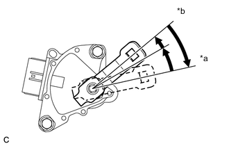
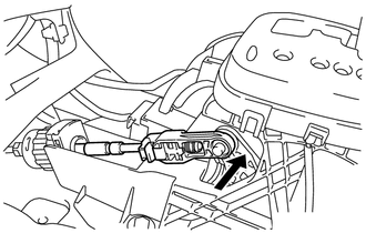
Text in Illustration *a P Position *b N Position Rotate the transmission control shaft lever clockwise until it stops, and then from that position rotate it counterclockwise by 2 notches to set it to the N position.
-
Connect the transmission control cable assembly to the transmission control shaft lever with the nut.
- Torque:
- 12 N*m { 122 kgf*cm, 9 ft.*lbf }
Note
To prevent damage to the transmission control cable assembly and the shift lever assembly, connect the transaxle side of the transmission control cable assembly before connecting the shift lever side.
-
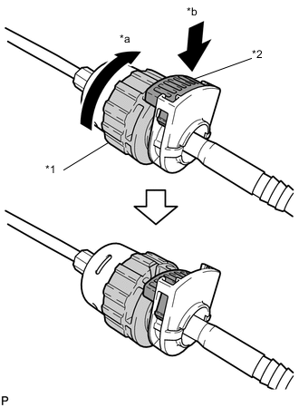
Text in Illustration *1 Nut *2 Lock *a Rotate approximately 180° *b Push in Rotate the nut of the transmission control cable assembly approximately 180° in the direction shown in the illustration, and while holding the nut, push in the lock.
Note
Rotating the nut too much will damage the internal spring, and the transmission control cable assembly will not be reusable. Do not turn the nut too far.
-
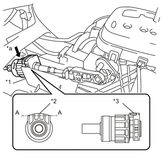
Text in Illustration *1 Shift Lever Plate *2 Projecting Part *3 Lock *a Push in Install the transmission control cable assembly to the shift lever plate.
Note
-
Install the cable outer with the projecting part facing upwards.
-
After installation, make sure that the cable outer lock is projecting from A as shown in the illustration.
-
Make sure that the transmission control cable assembly is securely locked.
Tech Tips
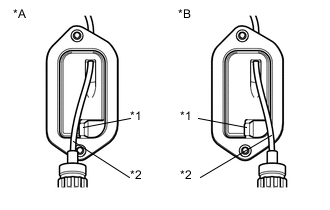
As shown in the illustration, the transmission control cable for LHD models passes along the left side of the projection, while the transmission control cable for RHD models passes along the right side of the projection.
-
-
Text in Illustration *A for LHD *B for RHD *1 Projection *2 Transmission Control Cable Confirm that the shift lever is in N, and then connect the cable end to the shift lever assembly.
Note
-
Securely install the cable end to the shift lever assembly.
-
Install the cable end so that its adjustment lock section is on the driver side.
-
-
-
ADJUST SHIFT LEVER POSITION
-
INSTALL FRONT NO. 1 FLOOR HEAT INSULATOR
-
Install the front No. 1 floor heat insulator to the body with the 2 bolts and nut.
- Torque:
- 5.5 N*m { 56 kgf*cm, 49 in.*lbf }
-
-
INSTALL FRONT EXHAUST PIPE ASSEMBLY
-
INSTALL FRONT FLOOR CENTER BRACE
-
INSPECT FOR EXHAUST GAS LEAK
-
INSPECT SHIFT LEVER POSITION
-
INSTALL REAR CONSOLE BOX
-
INSTALL ENGINE UNDER COVER LH