HYBRID VEHICLE TRANSAXLE INSTALLATION
PROCEDURE
-
INSTALL TRANSAXLE HSG AND CASE WITH HEAD STRAIGHT SCREW PLUG
-
Install a new gasket and the transaxle HSG and case with head straight screw plug to the hybrid vehicle transaxle assembly.
- Torque:
- 39 N*m { 400 kgf*cm, 29 ft.*lbf }
-
-
INSTALL WIRE HARNESS CLAMP BRACKET
-
Install the wire harness clamp bracket to the hybrid vehicle transaxle assembly with the bolt.
- Torque:
- 13 N*m { 130 kgf*cm, 9 ft.*lbf }
-
-
INSTALL TRANSMISSION CONTROL CABLE SUPPORT
-
Install the transmission control cable support and the No. 2 transmission control cable clamp to the hybrid vehicle transaxle assembly with the 3 bolts.
- Torque:
- 12 N*m { 122 kgf*cm, 9 ft.*lbf }
-
-
INSTALL MOTOR CABLE BRACKET
-
Install the motor cable bracket to the transmission control cable support with the bolt.
- Torque:
- 17 N*m { 173 kgf*cm, 13 ft.*lbf }
-
-
INSTALL AUTOMATIC TRANSMISSION CASE COVER
Tech Tips
Perform this procedure only when replacement of the automatic transmission case cover is necessary.
-
Install the automatic transmission case cover to the hybrid vehicle transaxle assembly with the 2 bolts.
- Torque:
- 13 N*m { 133 kgf*cm, 10 ft.*lbf }
-
-
INSTALL SHIFT LEVER POSITION SENSOR
Tech Tips
Perform this procedure only when replacement of the automatic transmission case cover is necessary.
-
Install the shift lever position sensor to the hybrid vehicle transaxle assembly.
Note
-
Do not reuse the shift lever position sensor if it has been dropped or subjected to a severe impact.
-
Do not allow moisture to adhere to the connector terminal.
-
-
Temporarily install the 2 bolts.
-
Install the lock plate and tighten the lock nut.
- Torque:
- 6.9 N*m { 70 kgf*cm, 61 in.*lbf }
-
Temporarily install the transmission control shaft lever to the shift lever position sensor.
-
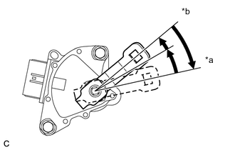
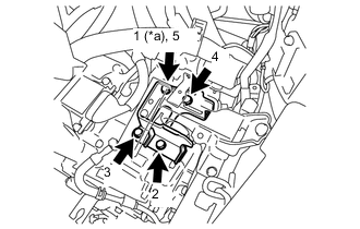
Text in Illustration *a P Position *b N Position Rotate the transmission control shaft lever clockwise until it stops, and then from that position rotate it counterclockwise by 2 notches to set it to the N position.
-
Remove the transmission control shaft lever from the shift lever position sensor.
-
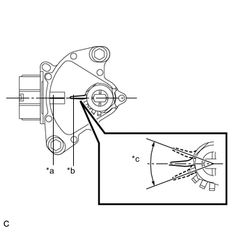
Text in Illustration *a Neutral Basic Line *b Protruding Part *c Range of Play Align the protruding part with the neutral basic line.
Note
There is play on the nut stopper side (protruding part). Align the center point of the range of the play with the neutral basic line.
-
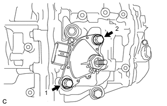
Tighten the 2 bolts in the order shown in the illustration.
- Torque:
- 13 N*m { 133 kgf*cm, 10 ft.*lbf }
-
Using a screwdriver, secure the lock nut with the lock plate.
-
-
INSTALL TRANSMISSION CONTROL SHAFT LEVER
-
Install the transmission control shaft lever to the shift lever position sensor with the washer and nut.
- Torque:
- 13 N*m { 130 kgf*cm, 9 ft.*lbf }
-
-
INSTALL TRANSMISSION CONTROL CABLE BRACKET
-
Install the transmission control cable bracket to the hybrid vehicle transaxle assembly with the 2 bolts.
- Torque:
- 12 N*m { 122 kgf*cm, 9 ft.*lbf }
-
-
INSTALL MOTOR CABLE
-
INSTALL MOTOR COOLING PIPE ASSEMBLY
-
Install a new O-ring and the union to the hybrid vehicle transaxle assembly.
- Torque:
- 27 N*m { 275 kgf*cm, 20 ft.*lbf }
-
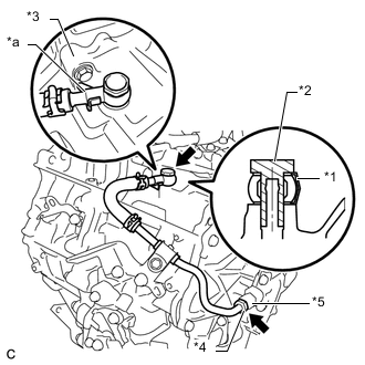
Text in Illustration *1 Gasket *2 Union Bolt *3 Transaxle Case *4 Flare Nut *5 Union *a Stopper Temporarily tighten the motor cooling pipe assembly to the hybrid vehicle transaxle assembly with a new gasket and the union bolt.
-
Temporarily tighten the flare nut of the motor cooling pipe assembly to the union.
-
Install the oil cooler tube clamp to the transmission control cable bracket with the bolt.
- Torque:
- 12 N*m { 117 kgf*cm, 8 ft.*lbf }
-
Fully tighten the union bolt with the motor cooling pipe assembly stopper pressed against the transaxle case.
- Torque:
- 35 N*m { 357 kgf*cm, 26 ft.*lbf }
-
Using a union nut wrench 17 mm, fully tighten the flare nut of the motor cooling pipe assembly.
- Torque:
- 34 N*m { 350 kgf*cm, 25 ft.*lbf }
Note
Use the formula to calculate special torque values for situations where the union nut wrench is combined with a torque wrench Click here.
Tech Tips
Turn the flare nut while holding the union.
-
-
INSTALL HYBRID VEHICLE TRANSAXLE ASSEMBLY
-
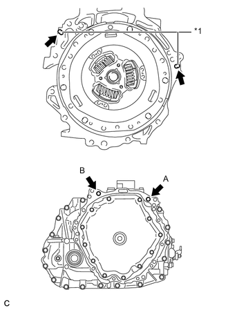
Text in Illustration *1 Knock Pin Make sure that the knock pins are installed to the engine assembly.
-
Temporarily install the hybrid vehicle transaxle assembly to the engine assembly with the 2 bolts.
Tech Tips
Temporarily tighten bolt B first.
-
Fully tighten the 2 bolts in the order of A and B.
- Torque:
- 64 N*m { 653 kgf*cm, 47 ft.*lbf }
Note
-
Make sure that the wire harness or similar items are not pinched between the contact surfaces.
-
Do not forcibly pry on the transaxle.
-
Make sure to align the transaxle so that the input shaft of the transaxle will be inserted straight into the inner splines of the transmission input damper.
-
Do not apply grease either to the inner splines of the transmission input damper assembly or to the outer splines of the input shaft.
-
When inserting the input shaft of the transaxle into the inner splines of the transmission input damper, do not shake the transaxle excessively.
-
When mounting the transaxle to the engine, make sure to securely fit the knock pins into the knock holes.
-
When tightening the bolts, be sure that the mating surfaces of the engine and the transaxle are in close contact with one another.
-
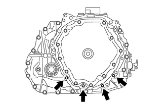
Install the 4 bolts.
- Torque:
- 30 N*m { 301 kgf*cm, 22 ft.*lbf }
-
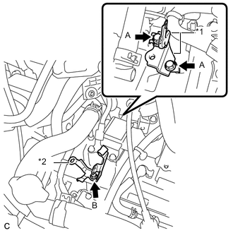
Text in Illustration *1 Wire Harness Clamp Bracket *2 No. 1 Transmission Control Cable Clamp Install the 2 wire harness clamp brackets and the No. 1 transmission control cable clamp to the hybrid vehicle transaxle assembly with the 3 bolts.
- Torque:
- Bolt A
- 13 N*m { 130 kgf*cm, 9 ft.*lbf }
- Bolt B
- 12 N*m { 122 kgf*cm, 9 ft.*lbf }
-
-
INSTALL TRANSVERSE ENGINE ENGINE MOUNTING BRACKET
-
Clean and degrease the bolts and bolt holes.
-
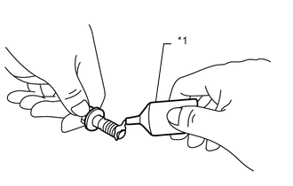
Text in Illustration *1 Adhesive Apply adhesive to 2 or 3 threads on the end of the 4 bolts.
Adhesive Toyota Genuine Adhesive 1324, Three Bond 1324 or equivalent Note
Apply adhesive to the bolts and tighten them within 3 minutes of application.
-
Text in Illustration *a Temporarily tighten Install the transverse engine engine mounting bracket to the hybrid vehicle transaxle assembly with the 4 bolts in the order shown in the illustration.
- Torque:
- 64 N*m { 653 kgf*cm, 47 ft.*lbf }
-
Install the transverse engine engine mounting bracket to the transverse engine engine mounting insulator with the through bolt and nut.
- Torque:
- 52 N*m { 530 kgf*cm, 38 ft.*lbf }
Tech Tips
Turn the through bolt while holding the nut.
-
-
INSTALL NO. 2 ENGINE MOVING CONTROL ROD
-
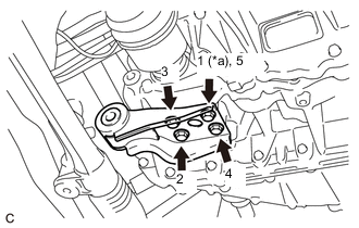
Text in Illustration *a Temporarily tighten Install the No. 2 engine moving control rod to the hybrid vehicle transaxle assembly with the 4 bolts in the order shown in the illustration.
- Torque:
- 45 N*m { 459 kgf*cm, 33 ft.*lbf }
-
-
INSTALL FRONT SUSPENSION CROSSMEMBER SUB-ASSEMBLY
-
INSTALL FLYWHEEL HOUSING SIDE COVER
-
Engage the claw and install the flywheel housing side cover to the engine assembly.
-
-
INSTALL STARTER HOLE INSULATOR
-
Install the starter hole insulator to the engine assembly with the 2 bolts.
- Torque:
- 30 N*m { 301 kgf*cm, 22 ft.*lbf }
-
-
INSTALL DRIVE SHAFT HEAT INSULATOR BRACKET
-
Install the drive shaft heat insulator bracket to the engine assembly with the 2 bolts.
- Torque:
- 30 N*m { 301 kgf*cm, 22 ft.*lbf }
-
Engage the clamp and install the wire harness to the drive shaft heat insulator bracket.
-
-
INSTALL DRIVE SHAFT HEAT INSULATOR SUB-ASSEMBLY
-
Install the drive shaft heat insulator sub-assembly to the engine assembly and the drive shaft heat insulator bracket with the bolt and nut.
- Torque:
- 18 N*m { 179 kgf*cm, 13 ft.*lbf }
-
-
INSTALL FRONT DRIVE SHAFT ASSEMBLY
-
INSTALL FRONT EXHAUST PIPE ASSEMBLY
-
INSTALL FRONT FLOOR CENTER BRACE
-
INSTALL NO. 1 STEERING COLUMN HOLE COVER SUB-ASSEMBLY
-
INSTALL STEERING INTERMEDIATE SHAFT ASSEMBLY
-
INSTALL COLUMN HOLE COVER SILENCER SHEET
-
INSTALL WIRE HARNESS
-
Engage the 7 clamps, connect the 4 connectors and install the wire harness to the hybrid vehicle transaxle assembly with the 3 bolts.
- Torque:
- 13 N*m { 130 kgf*cm, 9 ft.*lbf }
-
Engage the 4 clamps and install the No. 2 engine wire to the hybrid vehicle transaxle assembly.
-
-
INSTALL TRANSMISSION CONTROL CABLE ASSEMBLY
-
Install the transmission control cable assembly to the No. 1 transmission control cable clamp and the No. 2 transmission control cable clamp.
-
Install the transmission control cable assembly to the transmission control cable bracket with a new clip.
-
Connect the transmission control cable assembly to the transmission control shaft lever with the nut.
- Torque:
- 12 N*m { 122 kgf*cm, 9 ft.*lbf }
Note
To prevent damage to the transmission control cable assembly and the shift lever assembly, connect the transaxle side of the transmission control cable assembly before connecting the shift lever side.
-
-
CONNECT TRANSMISSION CONTROL CABLE ASSEMBLY
-
INSTALL INVERTER BRACKET ASSEMBLY
-
INSTALL INVERTER WITH CONVERTER ASSEMBLY
-
INSTALL OUTER COWL TOP PANEL (for LHD)
-
INSTALL OUTER COWL TOP PANEL (for RHD)
-
INSTALL INNER COWL TOP TO COWL BRACE (for LHD)
-
INSTALL INNER COWL TOP TO COWL BRACE (for RHD)
-
INSTALL FRONT NO. 1 VENTILATOR SEAL (for LHD)
-
INSTALL FRONT NO. 1 VENTILATOR SEAL (for RHD)
-
INSTALL FRONT AIR SHUTTER SEAL RH (for LHD)
-
INSTALL FRONT AIR SHUTTER SEAL RH (for RHD)
-
INSTALL WINDSHIELD WIPER MOTOR AND LINK ASSEMBLY
-
INSTALL SERVICE PLUG GRIP
-
ADD COOLANT (for Engine)
-
ADD COOLANT (for Inverter)
-
ADD HYBRID TRANSAXLE FLUID
-
INSPECT HYBRID TRANSAXLE FLUID
-
INSPECT FOR COOLANT LEAK (for Engine)
-
INSPECT FOR COOLANT LEAK (for Inverter)
-
INSPECT FOR HYBRID TRANSAXLE FLUID LEAK
-
INSPECT FOR EXHAUST GAS LEAK
-
INSTALL FRONT WHEELS
- Torque:
- 103 N*m { 1050 kgf*cm, 76 ft.*lbf }
-
INSPECT SHIFT LEVER POSITION
-
ADJUST SHIFT LEVER POSITION
-
INSPECT SHIFT LEVER POSITION SENSOR POSITION
-
ADJUST SHIFT LEVER POSITION SENSOR POSITION
-
INSTALL REAR CONSOLE BOX
-
INSTALL ENGINE UNDER COVER RH
-
INSTALL ENGINE UNDER COVER LH
-
INSPECT AND ADJUST FRONT WHEEL ALIGNMENT
-
CHECK SPEED SENSOR SIGNAL