IGNITION SWITCH INSPECTION
PROCEDURE
-
INSPECT IGNITION OR STARTER SWITCH ASSEMBLY
-
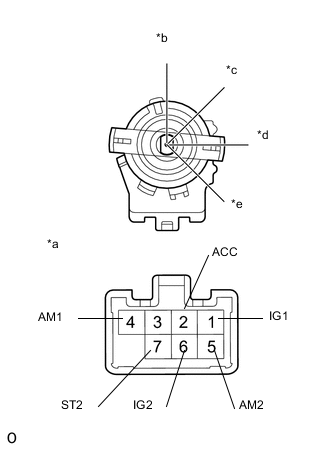
Text in Illustration *a Component without harness connected
(Ignition Switch Assembly)
*b LOCK *c ACC *d ON *e START Check the resistance.
-
Using an ohmmeter, measure the resistance between the terminals.
Standard resistance Tester Connection Switch Condition Specified Condition Between all terminals LOCK 10 kΩ or higher 2(ACC) - 4(AM1) ACC Below 1 Ω 1(IG1) - 2(ACC) - 4(AM1) ON Below 1 Ω 5(AM2) - 6(IG2) 1(IG1) - 4(AM1) READY Below 1 Ω 5(AM2) - 6(IG2) - 7(ST2) If the result is not as specified, replace the ignition switch assembly.
-
-