EXHAUST MANIFOLD INSTALLATION
PROCEDURE
-
INSTALL HEATED OXYGEN SENSOR
-
INSTALL NO. 2 EXHAUST MANIFOLD HEAT INSULATOR
-
Install the No. 2 exhaust manifold heat insulator with the 3 bolts.
- Torque:
- 8.0 N*m { 82 kgf*cm, 71 in.*lbf }
-
-
INSTALL EXHAUST MANIFOLD
-
Set a new gasket to the cylinder head sub-assembly.
-
Temporarily install the exhaust manifold with the 3 bolts and 2 nuts.
-
Temporarily install the manifold support bracket with the 3 bolts.
-
Tighten the exhaust manifold with the 3 bolts and 2 nuts.
- Torque:
- 30 N*m { 306 kgf*cm, 22 ft.*lbf }
-
Connect the wire harness clamp and heated oxygen sensor connector.
-
Remove the 3 bolts and manifold support bracket.
-
-
INSTALL NO. 1 EGR PIPE
-
Install a new gasket and No. 1 EGR pipe with the bolt and nut.
- Torque:
- 31 N*m { 316 kgf*cm, 23 ft.*lbf }
-
-
INSTALL MANIFOLD SUPPORT BRACKET
-
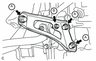
Install the manifold support bracket with the 4 bolts.
- Torque:
- Bolt A
- 44 N*m { 449 kgf*cm, 32 ft.*lbf }
- Bolt B
- 10 N*m { 102 kgf*cm, 7 ft.*lbf }
-
-
INSTALL NO. 1 EXHAUST MANIFOLD HEAT INSULATOR
-
Install the No. 1 exhaust manifold heat insulator with the 4 bolts.
- Torque:
- 8.0 N*m { 82 kgf*cm, 71 in.*lbf }
-
-
INSTALL AIR FUEL RATIO SENSOR
-
INSTALL FRONT EXHAUST PIPE ASSEMBLY
-
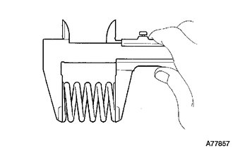
Using a vernier caliper, measure the free length of the compression springs.
Minimum (front) 41.5 mm (1.64 in.) Minimum (rear) 38.5 mm (1.52 in.) Tech Tips
If the free length is less than minimum, replace the compression spring.
-
Fully insert 2 new gaskets to the exhaust manifold converter and front exhaust pipe assembly.
-
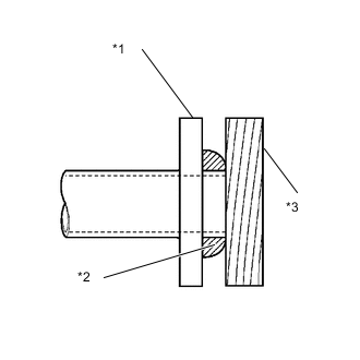
Text in Illustration *1 Exhaust Manifold and Front Exhaust Pipe Assembly *2 Gasket *3 Wooden Block Using a plastic hammer and wooden block, tap in each new gasket until its surface is flush with the exhaust manifold and front exhaust pipe assembly.
Note
-
Be careful with the installation direction of the gaskets.
-
Do not reuse the gaskets.
-
Do not damage the gaskets.
-
Do not push in the gaskets by using the exhaust pipe when connecting it.
-
-
Connect the front exhaust pipe assembly to the 3 exhaust pipe supports.
-
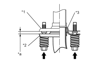
Install the front exhaust pipe assembly with the 2 compression springs and 2 bolts.
- Torque:
- 43 N*m { 438 kgf*cm, 32 ft.*lbf }
Tech Tips
After installation, check that the gaps between the flanges of the exhaust manifold and front exhaust pipe assembly are consistent front-to-rear and left-to-right.
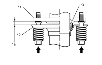
Text in Illustration *1 Exhaust Manifold *2 Front Exhaust Pipe Assembly *3 Gasket *a Space between flanges: 8.5 mm (0.335 in.) -
Install the front exhaust pipe assembly with the 2 compression springs and 2 bolts.
- Torque:
- 43 N*m { 438 kgf*cm, 32 ft.*lbf }
Tech Tips
After installation, check that the gaps between the flanges of the tail exhaust pipe assembly and front exhaust pipe assembly are consistent front-to-rear and left-to-right.
Text in Illustration *1 Tail Exhaust Pipe Assembly *2 Front Exhaust Pipe Assembly *3 Gasket *a Space between flanges: 6.5 mm (0.256 in.)
-
-
INSTALL FRONT FLOOR CENTER BRACE
-
Install the front floor brace center with the 2 bolts.
- Torque:
- 30 N*m { 307 kgf*cm, 22 ft.*lbf }
-
-
INSTALL EGR COOLER ASSEMBLY
-
INSPECT FOR EXHAUST GAS LEAK