OIL PUMP INSTALLATION

PROCEDURE
-
INSTALL OIL PUMP SEAL
-
Apply a light coat of MP grease to the timing chain cover oil pump seal lip.
Note
Keep the seal lip free of foreign matter.
-
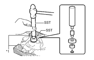
Text in Illustration *1 Wooden Block Using SST and a wooden block, tap in a new oil pump seal until its surface is flush with the timing chain cover edge.
- SST
- 09550-60010 ( 09951-00250, 09951-00380, 09952-06010 )
- 09950-70010
Tap in depth 0 to 1.0 mm from the edge of the timing chain cover. Note
Do not tap the oil pump seal at an angle.
-
-
INSTALL TIMING CHAIN COVER
-
Install 2 new O-rings to the cylinder block and oil pan.
-
Apply seal packing to the timing chain cover and engine assembly as shown in the illustration below.
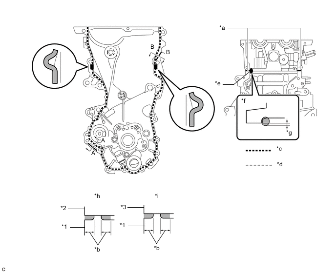
Text in Illustration *1 Timing Chain Cover *2 Cylinder Block *3 Cylinder Head Sub-assembly - - *a Apply Seal Packing to The Inner Corners *b 2.5 mm (0.0984 in.) or Higher *c Seal Packing Application Width 3.5 to 4.5 mm (0.138 to 0.177 in.) *d Seal Packing Application Width 1.5 to 2.0 mm (0.0591 to 0.0787 in.) *e Seal Packing Application Width 10 mm (0.394 in.) or more *f Upper View *g Apply enough seal packing so that it will protrude beyond the timing chain cover installation surface *h A - A (After Installation) *i B - B (After Installation) - - Seal packing Toyota Genuine Seal Packing Black, Three Bond 1207B or equivalent Note
-
Clean the surfaces with non-residue solvent before applying seal packing.
-
Install the timing chain cover within 3 minutes and tighten the bolts within 10 minutes of applying seal packing.
-
Do not apply engine oil for at least 2 hours after installation.
-
-
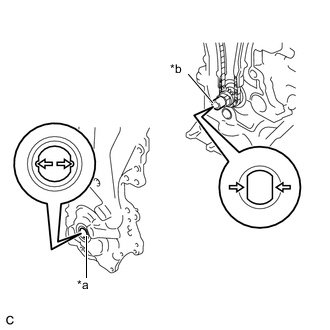
Text in Illustration *a Drive Rotor Spline *b Crankshaft Align the oil pump drive rotor spline and the crankshaft as shown in the illustration.
-
Temporarily install the timing chain cover and 2 wire harness clamp brackets with the 18 bolts and nut.
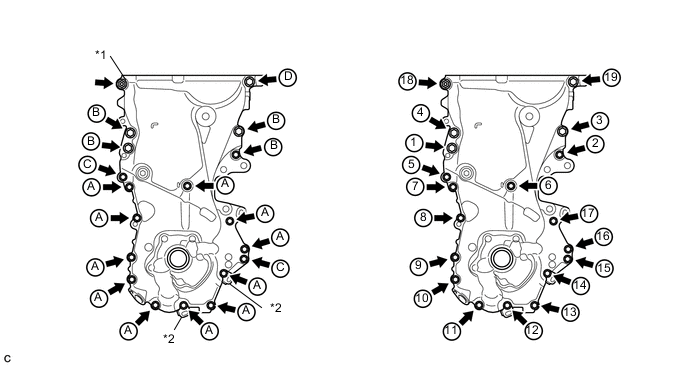
Text in Illustration *1 Nut *2 Wire Harness Clamp Bracket Bolt Length Item Length Thread Diameter Bolt A 20 mm (0.787 in.) 6 mm (0.236 in.) Bolt B 30 mm (1.18 in.) 8 mm (0.315 in.) Bolt C 35 mm (1.38 in.) 6 mm (0.236 in.) Bolt D 20 mm (0.787 in.) 8 mm (0.315 in.) Note
-
Be careful not to disturb the seal packing.
-
After installing the timing chain cover, install the engine mounting bracket RH within 10 minutes.
-
-
Tighten the 18 bolts and nut in the sequence shown in the illustration.
- Torque:
- Bolt A and Bolt C
- 12 N*m { 122 kgf*cm, 9 ft.*lbf }
- Bolt B
- 32 N*m { 326 kgf*cm, 24 ft.*lbf }
- Bolt D and Nut
- 24 N*m { 245 kgf*cm, 18 ft.*lbf }
-
-
INSTALL SCREW PLUG
-
Apply a few drops of adhesive to 2 or 3 threads of the screw plug.
Adhesive Toyota Genuine Adhesive 1324, Three Bond 1324 or equivalent -
Using an 8 mm hexagon socket wrench, install the screw plug.
- Torque:
- 15 N*m { 153 kgf*cm, 11 ft.*lbf }
-
-
INSTALL ENGINE MOUNTING BRACKET RH
-
Temporarily install the engine mounting bracket RH with the 4 bolts.
-
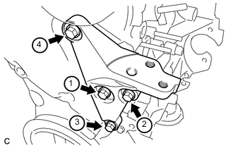
Tighten the 4 bolts in the sequence shown in the illustration.
- Torque:
- 55 N*m { 561 kgf*cm, 41 ft.*lbf }
-
-
INSTALL ENGINE OIL LEVEL DIPSTICK GUIDE
-
Apply a light coat of engine oil to a new O-ring and install the O-ring to the engine oil level dipstick guide.
-
Install the engine oil level dipstick guide with the bolt.
- Torque:
- 10 N*m { 102 kgf*cm, 7 ft.*lbf }
-
-
INSTALL ENGINE OIL LEVEL DIPSTICK
-
INSTALL CRANKSHAFT DAMPER SUB-ASSEMBLY
-
INSTALL CRANKSHAFT POSITION SENSOR
-
INSTALL CYLINDER HEAD COVER SUB-ASSEMBLY
-
INSTALL ENGINE COVER BRACKET
-
CONNECT ENGINE WIRE (for LHD)
-
CONNECT ENGINE WIRE (for RHD)
-
INSTALL NO. 1 IGNITION COIL
-
INSTALL EGR VALVE WITH COOLER ASSEMBLY
-
INSTALL NO. 2 EGR PIPE
-
REMOVE ENGINE STAND