FUEL TANK INSTALLATION
PROCEDURE
-
INSTALL FUEL TANK FILLER PIPE PROTECTOR
-
Engage the 4 claws and install the fuel tank filler pipe protector and No. 2 fuel tank filler pipe protector.
-
-
INSTALL FUEL HOSE CLAMP
-
Install the fuel hose clamp onto the fuel tank assembly.
-
-
REMOVE NO. 1 CANISTER OUTLET HOSE SUB-ASSEMBLY
-
Install the No. 1 canister outlet hose sub-assembly to the fuel tank assembly.
-
-
INSTALL FUEL TANK MAIN TUBE SUB-ASSEMBLY
-
Install the fuel tank main tube onto the fuel tank assembly.
-
-
INSTALL FUEL TANK ASSEMBLY
-
Clean and degrease the bolt holes.
-
Using an engine lifter, set the fuel tank assembly in the installation position.
Note
Do not drop the fuel tank.
-
Install the fuel tank assembly with 4 new bolts.
- Torque:
- 14 N*m { 146 kgf*cm, 11 ft.*lbf }
-
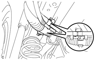
Install the 2 fuel hoses to the position shown in the illustration.
-
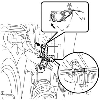
Text in Illustration *1 Fuel Tank Filler Pipe Flange Plate *2 Air Tube Install the fuel tank filler pipe flange plate as shown in the illustration.
-
Install the bolt.
- Torque:
- 34 N*m { 347 kgf*cm, 25 ft.*lbf }
-
Install the air tube as shown in the illustration.
-
-
CONNECT FUEL TANK MAIN TUBE SUB-ASSEMBLY
-
Align the fuel tube connector with the fuel pipe, connect the fuel tube connector and push the retainer in until the retainer makes a "click" sound to lock the claws of the retainer.
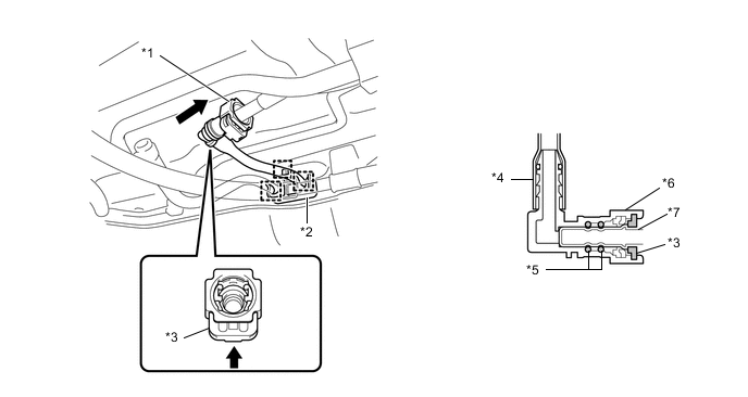
Text in Illustration *1 Fuel Tank Main Tube Sub-assembly *2 Fuel Tank Pipe Setting Holder *3 Retainer *4 Nylon Tube *5 O-ring *6 Fuel Tube Connector *7 Fuel Pipe 
Push Note
-
Check that there is no damage or foreign matter around the connecting parts of the fuel tube connector and fuel pipe before starting this step.
-
After connecting the fuel tube connector, check that the fuel tube connector is securely connected by pulling on the fuel tube connector.
-
-
Engage the 3 clamps and install the fuel tank pipe setting holder.
-
-
INSTALL NO. 1 FUEL TUBE PROTECTOR
-
Install the No. 1 fuel tube protector to the fuel tube connector.
-
-
CONNECT NO. 2 FUEL EMISSION TUBE
-
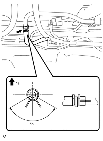
Text in Illustration *a Up *b 120° Connect the No. 2 fuel emission tube, then fit it with the clip as shown in the illustration.
Note
Check that there is no damage or foreign matter around the connecting parts of the No. 2 fuel emission tube and fuel pipe before performing this work.
-
-
INSTALL NO. 1 FUEL TANK PROTECTOR SUB-ASSEMBLY
-
Install the No. 1 fuel tank protector sub-assembly with the bolt and clip.
- Torque:
- 5.4 N*m { 55 kgf*cm, 48 in.*lbf }
-
-
INSTALL FRONT NO. 4 FLOOR HEAT INSULATOR
-
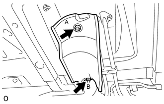
Install the front No. 4 floor heat insulator with the 2 nuts.
- Torque:
- Nut A
- 5.5 N*m { 56 kgf*cm, 49 in.*lbf }
- Nut B
- 5.4 N*m { 55 kgf*cm, 48 in.*lbf }
-
-
INSTALL FUEL TANK CAP ASSEMBLY
-
INSTALL FUEL SUCTION TUBE WITH PUMP AND GAUGE ASSEMBLY
-
ADD FUEL