FUEL PUMP REMOVAL

CAUTION / NOTICE / HINT
Tech Tips
Perform "Inspection After Repair" after replacing the fuel pump assembly Click here.
PROCEDURE
-
PRECAUTION
Note
After turning the ignition switch off, waiting time may be required before disconnecting the cable from the negative (-) auxiliary battery terminal. Therefore, make sure to read the disconnecting the cable from the negative (-) auxiliary battery terminal notice before proceeding with work Click here.
-
REMOVE CHILD RESTRAINT SEAT ANCHOR BRACKET SUB-ASSEMBLY
-
DISCHARGE FUEL SYSTEM PRESSURE
-
DISCONNECT CABLE FROM NEGATIVE AUXILIARY BATTERY TERMINAL
Note
When disconnecting the cable, some systems need to be initialized after the cable is reconnected Click here.
-
REMOVE REAR FLOOR SERVICE HOLE COVER
-
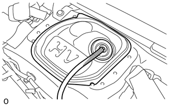
Remove the rear floor service hole cover.
-
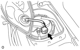
Disconnect the connector from the fuel suction tube assembly.
-
-
DISCONNECT FUEL TANK MAIN TUBE SUB-ASSEMBLY
-
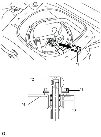
Text in Illustration *1 Tube Joint Clip *2 Fuel Tube Joint *3 O-ring *4 Fuel Suction Plate Remove the tube joint clip, then pull the fuel tube joint out of the plug of the fuel suction tube with pump and gauge assembly.
Note
-
Remove any dirt or foreign matter on the fuel tube joint before performing this work.
-
Do not allow any scratches or foreign matter to get on the parts when disconnecting them as the fuel tube joint has O-rings that seal the fuel pipe.
-
Only disconnect the fuel tube joint by hand.
-
Do not forcibly bend, twist or turn the fuel tank main tube sub-assembly.
-
Protect the disconnected part by covering it with a plastic bag after disconnecting the fuel tube joint.
-
If the fuel tube joint and fuel suction plate are stuck, push and pull to release them.
-
-
-
DISCONNECT NO. 2 FUEL EMISSION TUBE
-
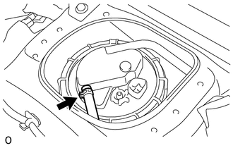
Loosen the clip and disconnect the No. 2 fuel emission tube from the fuel suction tube with pump and gauge assembly.
-
-
DISCONNECT NO. 1 CANISTER OUTLET HOSE SUB-ASSEMBLY
-
Disconnect the No. 1 canister outlet hose from the fuel suction tube with pump and gauge assembly.
-
-
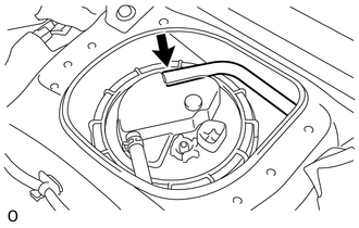
REMOVE FUEL PUMP GAUGE RETAINER
-
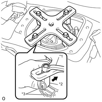
Text in Illustration *1 SST (Plate) *2 SST (Claw) *3 Rib 
Push Temporarily install the SST plate and claws to the fuel pump gauge retainer.
- SST
- 09808-14030 ( 09808-01030, 09808-01040, 09808-01050 )
Tech Tips
Engage the SST claws securely with the fuel pump gauge retainer ribs to secure SST.
-
While pressing the claws of SST to the fuel pump gauge retainer ribs securely, tighten the bolts.
Tech Tips
Install SST while pressing the SST claws toward the fuel pump gauge retainer (towards the center of SST).
-
Install the SST handle.
-
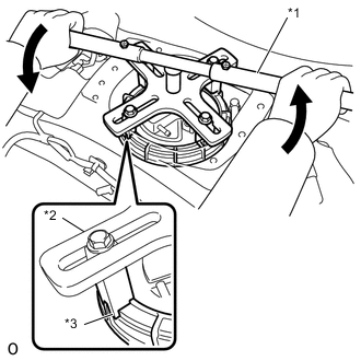
Text in Illustration *1 SST (Handle) *2 SST (Plate) *3 SST (Claw) Lightly press down on SST to prevent it from separating from the retainer. While pressing SST, rotate the handle slowly to loosen the retainer.
- SST
- 09808-14030 ( 09808-01010, 09808-01020, 09808-01030, 09808-01040, 09808-01050 )
Note
-
Do not use any tools other than specified in this operation. Damage to the fuel pump gauge retainer or the fuel tank may result.
-
Do not press down on SST excessively as this may make the retainer hard to rotate, and may damage components.
-
Make sure to rotate the SST handle horizontally. If the SST handle is rotated at an angle, SST may come off.
-
Do not spin SST too fast or use an impact wrench as this may result in damage to components.
-
If SST comes off of the retainer, loosen the SST bolts and reinstall SST.
Tech Tips
The ribs on the fuel pump gauge retainer can be fitted into the tips of SST.
-
Remove the fuel pump gauge retainer while holding the fuel suction tube with pump and gauge assembly by hand.
-
-
REMOVE FUEL SUCTION TUBE WITH PUMP AND GAUGE ASSEMBLY
-
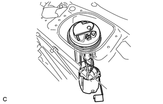
Remove the fuel suction tube with pump and gauge assembly from the fuel tank.
Note
Make sure that the fuel sender gauge arm does not bend.
-
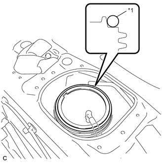
Text in Illustration *1 Fuel Suction Tube Set Gasket Remove the fuel suction tube set gasket from the fuel tank.
-