FUEL INJECTOR INSTALLATION

PROCEDURE
-
INSTALL FUEL INJECTOR ASSEMBLY
-
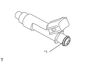
Text in Illustration *1 O-ring Apply a light coat of gasoline or spindle oil to new O-rings, and then install one onto each fuel injector.
-
Apply a light coat of gasoline or spindle oil to the contact surfaces of the new O-ring on each fuel injector assembly.
-
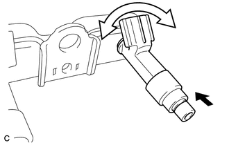
While turning the fuel injector assembly left and right, install it onto the fuel delivery pipe sub-assembly.
Text in Illustration 
Push 
Turn Note
-
Make sure that the O-ring is not cracked or jammed when installing the injector Click here.
-
If a component has been dropped or subjected to a strong impact, replace it.
Tech Tips
Perform "Inspection After Repairs" after replacing the fuel injector assembly Click here.
-
-
Check that the fuel injector rotates smoothly. If the fuel injector does not rotate, replace the O-ring.
-
-
INSTALL INJECTOR VIBRATION INSULATOR
-
Install 4 new injector vibration insulators onto the cylinder head.
-
-
INSTALL FUEL DELIVERY SPACER
-
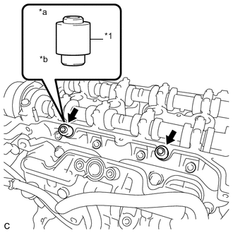
Text in Illustration *1 Fuel Delivery Spacer *a Fuel Delivery Pipe Side *b Cylinder Head Side Install the 2 fuel delivery spacers onto the cylinder head.
Note
Install the fuel delivery spacer in the correct direction.
-
-
INSTALL FUEL DELIVERY PIPE
-
Install the fuel delivery pipe with the 4 fuel injector assemblies and install the 2 bolts.
- Torque:
- 21 N*m { 214 kgf*cm, 15 ft.*lbf }
Note
-
Do not drop the fuel injectors when installing the fuel delivery pipe.
-
Check that the fuel injector assemblies rotate smoothly after installing the fuel delivery pipe.
-
Engage the clamp to connect the wire harness.
-
Install the bolt to secure the fuel delivery pipe.
- Torque:
- 10 N*m { 102 kgf*cm, 7 ft.*lbf }
-
-
CONNECT FUEL TUBE SUB-ASSEMBLY
-
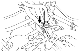
Push the tube connector into the pipe until the tube connector makes a "click" sound.
Text in Illustration Push Note
-
Before connecting the fuel tube connector and fuel delivery pipe, check that there is no damage or foreign matter on the connecting part of the fuel delivery pipe.
-
After connecting the fuel tube connector and fuel delivery pipe, check that they are securely connected by trying to pull them apart.
-
-
-
INSTALL EFI FUEL PIPE CLAMP
-
Install the EFI fuel pipe clamp.
-
-
INSTALL CYLINDER HEAD COVER SUB-ASSEMBLY
-
CONNECT ENGINE WIRE (for LHD)
-
CONNECT ENGINE WIRE (for RHD)
-
INSTALL BRAKE MASTER CYLINDER RESERVOIR ASSEMBLY
-
INSTALL NO. 1 IGNITION COIL
-
INSTALL EGR VALVE WITH COOLER ASSEMBLY
-
INSTALL ENGINE COVER BRACKET
-
CONNECT CABLE TO NEGATIVE AUXILIARY BATTERY TERMINAL
- Torque:
- 5.4 N*m { 55 kgf*cm, 47 in.*lbf }
Note
When disconnecting the cable, some systems need to be initialized after the cable is reconnected Click here.
-
INSTALL FRONT FLOOR COVER RH (for Front Floor Cover Type A)
-
INSTALL FRONT FLOOR COVER RH (for Front Floor Cover Type B)
-
INSTALL CENTER FRONT FLOOR COVER (for Front Floor Cover Type B)
-
INSPECT FOR FUEL LEAK
-
INSPECT FOR ENGINE OIL LEAK
-
INSTALL NO. 2 CYLINDER HEAD COVER (w/ No. 2 Cylinder Head Cover)