CYLINDER BLOCK REASSEMBLY

PROCEDURE
-
INSTALL OIL JET
-
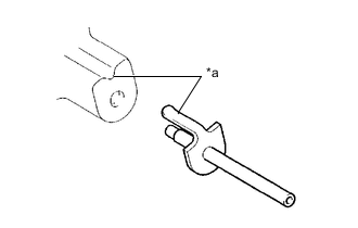
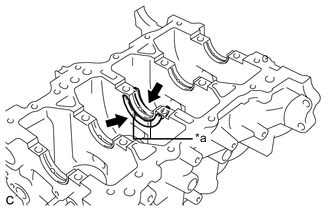
Text in Illustration *a Align Align the concave part of the cylinder block with the bracket of a new oil jet, then tap in the oil jet (the service part).
Note
Do not tap the tip of the oil jet.
-
-
INSTALL WATER BY-PASS HOSE UNION
-
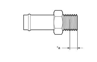
Text in Illustration *a 6.0 mm (0.236 in.) Apply adhesive as shown in the illustration.
Adhesive Toyota Genuine Adhesive 1324, Three Bond 1324 or equivalent -
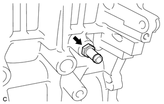
Using a 17 mm deep socket wrench, install the water by-pass hose union to the cylinder block.
- Torque:
- 35 N*m { 357 kgf*cm, 26 ft.*lbf }
Note
-
Install the water by-pass hose union within 3 minutes of applying adhesive.
-
Do not add coolant for at least 1 hour after installation.
-
-
INSTALL CRANKSHAFT BEARING
-
Clean the main journal and both surfaces of the crankshaft bearing.
-
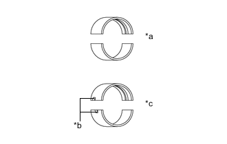
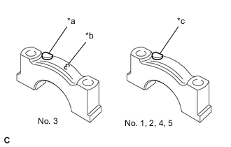
Text in Illustration *a Mass Production Part *b Claw *c Service Part Mass production parts do not have claws if reusing mass production parts, measure the clearance of both sides with the crankshaft bearings in the center of the crankshaft bearing caps.
-
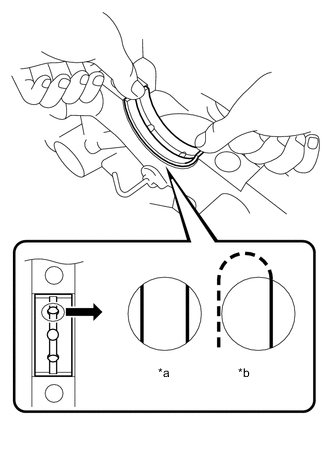
Text in Illustration *a CORRECT *b INCORRECT Install the upper crankshaft bearing to the cylinder block as shown in the illustration.
Note
-
Both sides of the oil groove in the cylinder block should be visible through the oil feed holes in the upper crankshaft bearing. The amount visible on each side of the holes should be equal.
-
Do not apply engine oil to the bearings or their contact surfaces.
-
-
Install the lower crankshaft bearing onto the crankshaft bearing cap.
Note
Do not apply engine oil to the bearings and the contact surfaces.
-
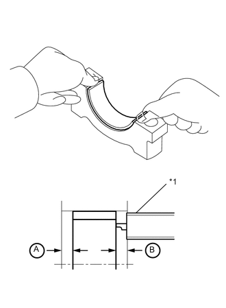
Text in Illustration *1 Vernier Caliper Using a vernier caliper, measure the distance between the crankshaft bearing caps edge and the lower crankshaft bearings edge.
Standard dimension A - B or B - A 0 to 0.7 mm (0 to 0.0276 in.)
-
-
INSTALL UPPER CRANKSHAFT THRUST WASHER
-
Text in Illustration *a Oil Groove Install the 2 upper crankshaft thrust washers onto the No. 3 journal position of the cylinder block with the oil grooves facing outward.
-
-
INSTALL CRANKSHAFT
Tech Tips
The crankshaft bearing cap bolts are tightened in 2 progressive steps.
-
Apply engine oil to the upper crankshaft bearings and install the crankshaft onto the cylinder block.
-
Text in Illustration *a Front Mark *b Number *c Front Mark and Number Check the front marks and numbers and install the crankshaft bearing caps onto the cylinder block.
-
Apply a light coat of engine oil to the lower crankshaft bearings and threads of the crankshaft bearing cap bolts.
-
Step 1:
-
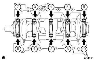
Using several steps, uniformly tighten and install the 10 crankshaft bearing cap bolts with 12 mm socket wrench for 12 pointed head in the sequence shown in the illustration.
- Torque:
- 22 N*m { 224 kgf*cm, 16 ft.*lbf }
-
-
Step 2:
-
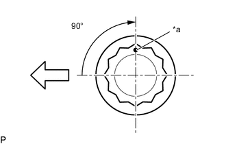
Text in Illustration *a Paint Mark 
Engine Front Mark each crankshaft bearing cap bolts head with a paint mark as shown in the illustration.
-
Tighten the crankshaft bearing cap bolts 90° in the sequence shown in step 1.
-
-
Check that the paint mark is now at a 90° angle to the front.
-
Check that the crankshaft turns smoothly.
-
-
INSTALL PISTON SUB-ASSEMBLY WITH PISTON PIN
Tech Tips
Perform "Inspection After Repairs" after replacing the piston sub-assembly Click here.
-
Heat the piston to approximately 80 to 90°C (176 to 194°F).
CAUTION:
Use gloves to protect your hands as the piston is hot.
-
Apply engine oil to the piston pin and the inside surface of the connecting rod sub-assembly.
-
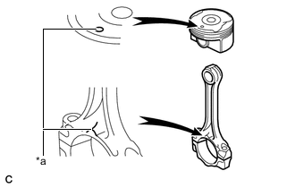
Text in Illustration *a Front Mark Align the front marks of the piston sub-assembly and connecting rod sub-assembly.
-
Using SST, push in the piston pin.
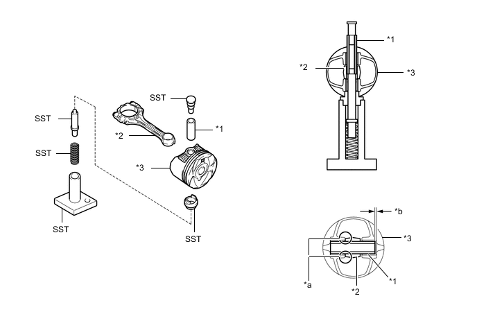
Text in Illustration *1 Piston Pin *2 Connecting Rod Sub-assembly *3 Piston Sub-assembly *a Press *b 1.25 to 2.25 mm (0.0492 to 0.0886 in.) - SST
- 09221-25026 ( 09221-00021, 09221-00030, 09221-00061, 09221-00090, 09221-00100 )
Note
-
The piston sub-assembly and piston pin are a matched set.
-
With the connecting rod fully inserted into the piston end, press in the piston pin until it is flush with the piston surface.
-
Check the fitting condition between the piston sub-assembly and piston pin by trying to move the piston back and forth on the piston pin.
-
-
INSTALL CONNECTING ROD BEARING
-
Text in Illustration *a Claw Align the connecting rod bearing claw with the grooves of the connecting rod and connecting rod cap.
Note
Do not apply engine oil to the contact surface of the connecting rod and connecting rod cap or the backside of the connecting rod bearing.
-
-
INSTALL PISTON RING SET
Tech Tips
Perform "Inspection After Repairs" after replacing the piston ring Click here.
-
Install the oil ring expander and 2 side rails by hand.
-
Text in Illustration *a Code Mark *b Paint Mark 
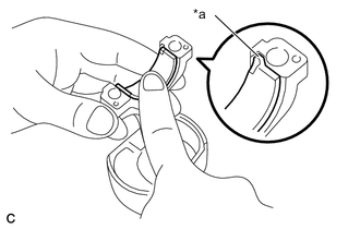
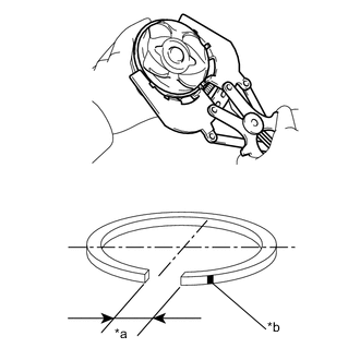
Up Using a piston ring expander, install the No. 2 compression ring as shown in the illustration.
Piston Ring Mark Part Paint Mark Code Mark No. 2 compression ring Blue 2R Note
Install the No. 2 compression ring with the code mark facing upward.
-
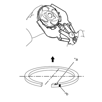
Text in Illustration *a Compression Ring Ends *b Paint Mark Using a piston ring expander, install the No. 1 compression ring as shown in the illustration.
Piston Ring Mark Part Paint Mark Code Mark No. 1 compression ring Red - Note
Place a paint mark on the right side of the opening.
-
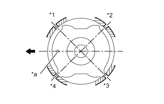
Text in Illustration *1 No. 1 Compression Ring and Oil Ring Expander *2 Lower Side Rail *3 No. 2 Compression Ring *4 Upper Side Rail *a Front Mark Engine Front Position the piston rings so that the ring ends are as shown in the illustration.
-
-
INSTALL PISTON SUB-ASSEMBLY WITH CONNECTING ROD
Tech Tips
The connecting rod cap bolts are tightened in 2 progressive steps.
-
Apply engine oil to the cylinder walls, pistons, and surfaces of the connecting rod bearings.
Note
Do not apply engine oil to the contact surface of the connecting rod and connecting rod cap or the backside of the connecting rod bearing.
-
Check the position of the piston ring ends.
-
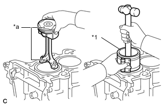
Text in Illustration *1 Piston Ring Compressor *a Front Mark Using a piston ring compressor, push the correct piston sub-assembly and connecting rod sub-assembly into each cylinder with the front mark on the piston facing forward.
-
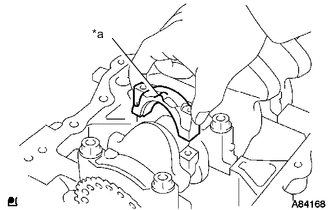
Text in Illustration *a Front Mark Check that the front mark of the connecting rod cap is facing forward and install the connecting rod cap.
-
Apply a light coat of engine oil to the threads of the connecting rod cap bolts.
-
Step 1:
-
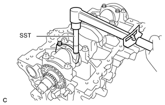
Using SST, install and alternately tighten the connecting rod cap bolts of the connecting rod cap in several steps.
- Torque:
- 15 N*m { 153 kgf*cm, 11 ft.*lbf }
- SST
- 09205-16010
-
-
Step 2:
-
Text in Illustration *a Paint Mark Engine Front Mark each connecting rod cap bolts head with a paint mark as shown in the illustration.
-
Tighten the connecting rod cap bolts 90° in the sequence shown in step 1.
-
-
Check that the paint mark is now at a 90° angle to the front.
-
Check that the crankshaft turns smoothly.
-