CYLINDER BLOCK INSPECTION

PROCEDURE
-
INSPECT CRANKSHAFT OIL CLEARANCE
-
Clean the crank journal and crankshaft bearing cap.
-
Install the crankshaft bearing Click here.
-
Install the crankshaft Click here.
-
Text in Illustration *1 Plastigage Lay a strip of Plastigage across each journal.
-
Install the crankshaft bearing cap Click here.
Note
Do not turn crankshaft.
-
Remove the crankshaft bearing cap Click here.
-
Text in Illustration *1 Plastigage Measure the Plastigage at its widest point.
Standard oil clearance 0.010 to 0.026 mm (0.000394 to 0.00102 in.) Maximum oil clearance 0.07 mm (0.00276 in.) Note
Completely remove the Plastigage.
-
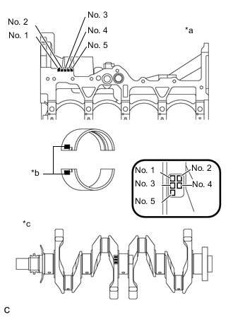
Text in Illustration *a Cylinder Block Number *b Bearing Number *c Crank Journal Number If the oil clearance is greater than the maximum, select and replace the crankshaft bearing. If necessary, use an undersized main bearing.
Tech Tips
-
To select the correct main bearing size, calculate the crankshaft bearing number by adding together the numbers imprinted on the cylinder block and crankshaft.
-
Number on the cylinder block is 3. Number on the crankshaft is 5. 3 + 5 = 8 Select bearing number 3.
Reference Number Cylinder Block Diameter Crankshaft Journal Diameter 0 50.000 to 50.003 mm (1.9685 to 1.9686 in.) 45.998 to 46.000 mm (1.8109 to 1.8110 in.) 1 50.003 to 50.005 mm (1.9686 to 1.9687 in.) 45.996 to 45.998 mm (1.81086 to 1.81094 in.) 2 50.005 to 50.007 mm (1.9687 to 1.9688 in.) 45.994 to 45.996 mm (1.8108 to 1.8109 in.) 3 50.007 to 50.010 mm (1.9688 to 1.9689 in.) 45.992 to 45.994 mm (1.8107 to 1.8108 in.) 4 50.010 to 50.012 mm (1.9689 to 1.9690 in.) 45.990 to 45.992 mm (1.8106 to 1.8107 in.) 5 50.012 to 50.014 mm (1.9690 to 1.9691 in.) 45.988 to 45.990 mm (1.8105 to 1.8106 in.) 6 50.014 to 50.016 mm (1.96905 to 1.96913 in.) - Reference Cylinder Block Number + Crank Journal Number Bearing Number Center Bearing Thickness Oil Clearance 0 to 2 1 1.992 to 1.995 mm (0.0784 to 0.0785 in.) 0.010 to 0.026 mm (0.000394 to 0.00102 in.) 3 to 5 2 1.995 to 1.998 mm (0.0785 to 0.0787 in.) 0.010 to 0.026 mm (0.000394 to 0.00102 in.) 6 to 8 3 1.998 to 2.001 mm (0.0787 to 0.0788 in.) 0.010 to 0.026 mm (0.000394 to 0.00102 in.) 9 to 11 4 2.001 to 2.004 mm (0.0788 to 0.0789 in.) 0.010 to 0.026 mm (0.000394 to 0.00102 in.) - U/S 0.25 2.111 to 2.117 mm (0.0831 to 0.0834 in.) 0.010 to 0.026 mm (0.000394 to 0.00102 in.) -
-
-
INSPECT CYLINDER BLOCK FOR WARPAGE
-
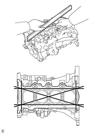
Using a precision straightedge and feeler gauge, measure the warpage of the surface that is in contact with the cylinder head gasket.
Maximum warpage 0.05 mm (0.00197 in.) If the warpage is greater than the maximum, replace the cylinder block.
-
-
INSPECT CYLINDER BORE
-
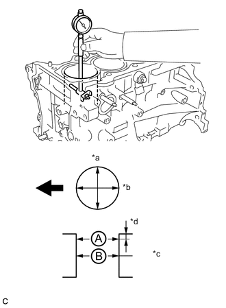
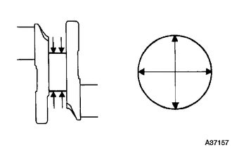
Text in Illustration *a Thrust Direction *b Axial Direction *c Center *d 10 mm (0.394 in.) 
Engine Front Using a cylinder gauge, measure the cylinder bore diameter at positions A and B in the thrust and axial directions.
Standard diameter 75.000 to 75.013 mm (2.9528 to 2.9533 in.) Maximum diameter 75.133 mm (2.9580 in.) If the average diameter of the 4 positions is greater than the maximum, replace the cylinder block.
-
-
INSPECT CONNECTING ROD SUB-ASSEMBLY
-
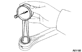
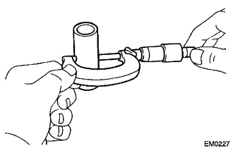
Using a caliper gauge, measure the internal diameter of the connecting rod sub-assembly.
Standard connecting rod inside diameter 17.965 to 17.985 mm (0.707 to 0.708 in.) If the diameter is not within the range of the standard inside diameter, replace the connecting rod sub-assembly.
-
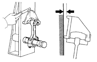
Using a rod aligner and feeler gauge, check the connecting rod sub-assembly alignment.
-
Check for misalignment.
Maximum misalignment 0.05 mm (0.0020 in.) per 100 mm (3.94 in.) If the misalignment is greater than the maximum, replace the connecting rod sub-assembly.
-
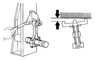
Check for twist.
Maximum twist 0.05 mm (0.0020 in.) per 100 mm (3.94 in.) If the twist is greater than the maximum, replace the connecting rod sub-assembly.
-
-
-
INSPECT PISTON AND PISTON PIN
-
Clean the piston and piston pin.
-
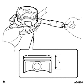
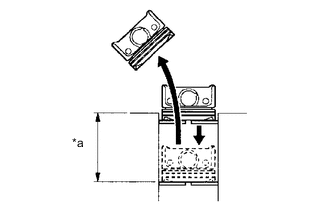
Text in Illustration *a 37 mm (1.46 in.) Using a micrometer, measure the piston diameter at right angles to the piston pin hole, and at a point 37 mm (1.46 in.) from the piston bottom.
Standard piston diameter 74.969 to 74.991 mm (2.9515 to 2.9524 in.) If the diameter is not as specified, replace the piston.
-
Using a caliper gauge, measure the piston pin hole diameter of the piston.
Standard piston pin hole diameter 18.013 to 18.016 mm (0.70917 to 0.70929 in.) at 20°C (68°F) If the diameter is not as specified, replace the piston.
-
Using a micrometer, measure the piston pin diameter.
Standard piston pin diameter 18.001 to 18.004 mm (0.70870 to 0.70881 in.) -
Subtract the piston pin diameter measurement from the piston pin hole diameter measurement.
Standard oil clearance 0.009 to 0.015 mm (0.000354 to 0.000591 in.) Maximum oil clearance 0.05 mm (0.00197 in.) If the clearance is greater than the maximum, replace both the piston and piston pin together.
-
-
INSPECT PISTON OIL CLEARANCE
-
Subtract the piston diameter measurement from the cylinder bore diameter measurement.
Standard oil clearance 0.009 to 0.044 mm (0.000354 to 0.00173 in.) Maximum oil clearance 0.08 mm (0.00315 in.) If the oil clearance is greater than the maximum, replace all the pistons. If necessary, replace the cylinder block.
-
-
INSPECT RING GROOVE CLEARANCE
-
Using a feeler gauge, measure the clearance between a new piston ring and the wall of the ring groove.
Standard ring groove clearance Item Specified Condition No. 1 ring 0.02 to 0.07 mm (0.000787 to 0.00276 in.) No. 2 ring 0.02 to 0.06 mm (0.000787 to 0.00236 in.) Oil ring 0.07 to 0.13 mm (0.00276 to 0.00512 in.) If the groove clearance is not as specified, replace the piston.
-
-
INSPECT PISTON RING END GAP
-
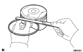
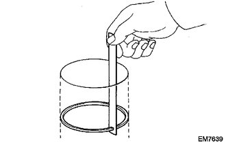
Text in Illustration *a 110 mm (4.33 in.) Using a piston, push the piston ring a little beyond the bottom of the ring travel, 110 mm (4.33 in.) from the top of the cylinder block.
-
Using a feeler gauge, measure the end gap.
Standard end gap Item Standard Maximum No. 1 ring 0.18 to 0.28 mm (0.00709 to 0.0110 in.) 0.59 mm (0.0232 in.) No. 2 ring 0.28 to 0.43 mm (0.0110 to 0.0169 in.) 1.18 mm (0.0465 in.) Oil ring 0.10 to 0.35 mm (0.00394 to 0.0138 in.) 1.13 mm (0.0445 in.) If the end gap is greater than the maximum, replace the piston ring and oil ring.
-
-
INSPECT CONNECTING ROD BOLT
-
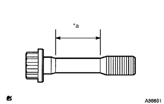
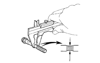
Text in Illustration *a Measurement Area Using a vernier caliper, measure the tension portion diameter of the bolt.
Standard diameter 6.6 to 6.7 mm (0.260 to 0.264 in.) Minimum diameter 6.4 mm (0.252 in.) If the diameter is less than the minimum, replace the bolt.
-
-
INSPECT CRANKSHAFT
-
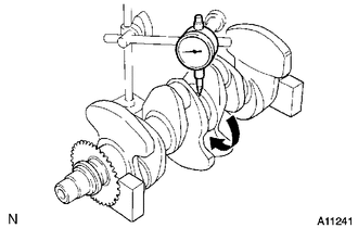
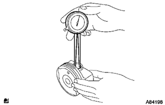
Using a dial indicator and V-blocks, measure the circle runout as shown in the illustration.
Maximum circle runout 0.03 mm (0.00118 in.) If the circle runout is greater than the maximum, replace the crankshaft.
-
Inspect the diameter.
-
Using a micrometer, measure the diameter of each main journal as illustrated.
Standard diameter 45.988 to 46.000 mm (1.8105 to 1.8110 in.) If the diameter is not as specified, replace the crankshaft.
-
Calculate the taper and distortion of the main journal.
Maximum taper and distortion 0.02 mm (0.000787 in.) If the taper or distortion is greater than the maximum, replace the crankshaft.
-
Using a micrometer, measure the diameter of each crank pin as illustrated.
Standard diameter 39.992 to 40.000 mm (1.5745 to 1.5748 in.) If the diameter is not as specified, replace the crankshaft.
-
Calculate the taper and distortion of the crank pin.
Maximum taper and distortion 0.02 mm (0.000787 in.) If the taper or distortion is greater than the maximum, replace the crankshaft.
-
-
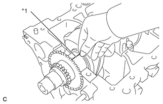
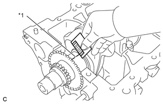
Wrap the chain sub-assembly around the timing sprocket.
-
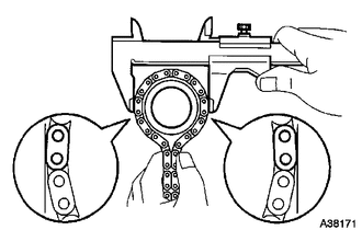
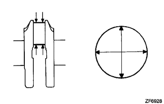
Using a vernier caliper, measure the diameter of the timing sprocket with the chain sub-assembly.
Standard sprocket diameter 51.72 mm (2.04 in.) Minimum sprocket diameter 50.5 mm (1.99 in.) Note
When measuring the diameter, the vernier caliper must be in contact with the chain rollers.
If the diameter is less than the minimum, replace the chain and crankshaft.
-
-
INSPECT CRANKSHAFT BEARING CAP SET BOLT
-
Using a vernier caliper, measure the tension portion diameter of the bolt.
Standard diameter 7.3 to 7.5 mm (0.287 to 0.295 in.) Minimum diameter 7.3 mm (0.287 in.) If the diameter is less than the minimum, replace the bolt.
-