CYLINDER BLOCK DISASSEMBLY

PROCEDURE
-
INSPECT CONNECTING ROD THRUST CLEARANCE
-
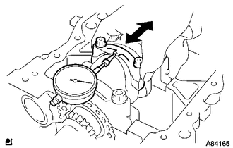
Using a dial indicator, measure the thrust clearance while moving the connecting rod back and forth.
Standard thrust clearance 0.16 to 0.36 mm (0.00630 to 0.0142 in.) Maximum thrust clearance 0.36 mm (0.0142 in.) If the thrust clearance is greater than the maximum, replace the connecting rod.
-
-
INSPECT CONNECTING ROD OIL CLEARANCE
-
Mark each cylinder No. on the connecting rod and connecting rod cap with paint.
-
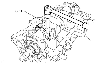
Using SST, remove the 2 connecting rod cap bolts.
- SST
- 09205-16010
-
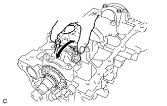
Using the 2 removed connecting rod cap bolts, remove the connecting rod cap with connecting rod bearing by wiggling the connecting rod cap right and left.
-
Clean the crank pin and connecting rod bearing.
Note
Check the crank pin and connecting rod bearing for pitting and scratches.
-
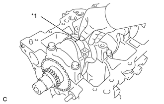
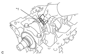
Text in Illustration *1 Plastigage Lay a strip of Plastigage across the crank pin.
-
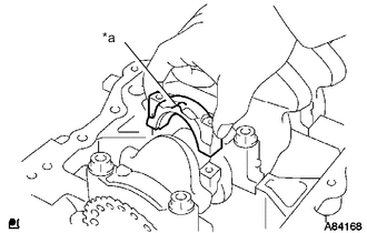
Text in Illustration *a Front Mark Check that the front mark of the connecting rod cap is facing forward and install the connecting rod cap.
-
Apply a light coat of engine oil to the threads of the connecting rod cap bolts.
-
Step 1:
-
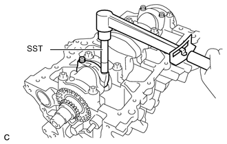
Using SST, install and alternately tighten the connecting rod cap bolts of the connecting rod cap in several steps.
Note
Do not turn crankshaft.
- Torque:
- 15 N*m { 153 kgf*cm, 11 ft.*lbf }
- SST
- 09205-16010
-
-
Step 2:
-
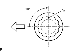
Text in Illustration *a Paint Mark 
Engine Front Mark each connecting rod cap bolts head with a paint mark as shown in the illustration.
Note
Do not turn crankshaft.
-
Tighten the connecting rod cap bolts 90° in the sequence shown in step 1.
-
-
Remove the connecting rod cap.
-
Text in Illustration *1 Plastigage Measure the Plastigage at its widest point.
Standard oil clearance 0.012 to 0.038 mm (0.000472 to 0.00150 in.) Maximum oil clearance 0.06 mm (0.00236 in.) Note
Completely remove the Plastigage.
-
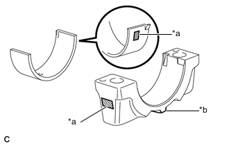
Text in Illustration *a Number Mark *b Front Mark If the oil clearance is greater than the maximum, select and replace the connecting rod bearings. If necessary, use an undersized bearing.
Reference Number Mark Connecting Rod External Diameter Center Bearing Thickness Oil Clearance 1 43.000 to 43.008 mm (1.6929 to 1.6932 in.) 1.488 to 1.492 mm (0.058583 to 0.058740 in.) 0.012 to 0.038 mm (0.000472 to 0.00150 in.) 2 43.008 to 43.016 mm (1.6932 to 1.6935 in.) 1.492 to 1.496 mm (0.058740 to 0.058898 in.) 0.012 to 0.038 mm (0.000472 to 0.00150 in.) 3 43.016 to 43.024 mm (1.6935 to 1.6939 in.) 1.496 to 1.500 mm (0.058898 to 0.059055 in.) 0.012 to 0.038 mm (0.000472 to 0.00150 in.) U/S 0.25 43.000 to 43.024 mm (1.6929 to 1.6939 in.) 1.610 to 1.614 mm (0.063386 to 0.063543 in.) 0.013 to 0.059 mm (0.000512 to 0.00232 in.)
-
-
REMOVE PISTON SUB-ASSEMBLY WITH CONNECTING ROD
-
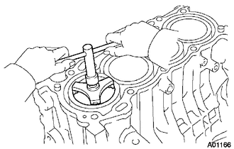
Using a ridge reamer, remove all carbon from the top of the cylinder.
-
Push the piston, connecting rod and connecting rod bearing through the top of the cylinder block.
Tech Tips
-
Keep each connecting rod bearing, connecting rod and connecting rod cap as a set.
-
Arrange the removed parts in the correct order.
-
-
-
INSPECT CRANKSHAFT THRUST CLEARANCE
-
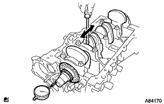
Using a dial indicator, measure the thrust clearance while prying the crankshaft back and forth with a screwdriver.
Standard thrust clearance 0.04 to 0.24 mm (0.00157 to 0.00945 in.) Maximum thrust clearance 0.3 mm (0.0118 in.) If the thrust clearance is greater than the maximum, replace the thrust washers as a set.
Reference Item Thrust Washer Thickness Thrust Clearance STD 2.43 to 2.48 mm (0.0957 to 0.0976 in.) 0.04 to 0.24 mm (0.00157 to 0.00945 in.) O/S 0.125 2.493 to 2.543 (0.0981 to 0.100 in.) 0.04 to 0.24 mm (0.00157 to 0.00945 in.) O/S 0.250 2.555 to 2.605 (0.101 to 0.103 in.) 0.04 to 0.24 mm (0.00157 to 0.00945 in.)
-
-
REMOVE CONNECTING ROD BEARING
-
Remove the 8 connecting rod bearings.
Tech Tips
Arrange the removed parts in the correct order.
-
-
REMOVE PISTON RING SET
-
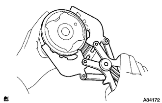
Using a piston ring expander, remove the No. 1 compression ring and No. 2 compression ring.
-
Remove the oil ring expander and 2 side rails by hand.
Tech Tips
Arrange the removed parts in the correct order.
-
-
REMOVE PISTON SUB-ASSEMBLY WITH PISTON PIN
-
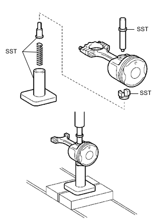
Using SST, press out the piston pin from the piston.
- SST
- 09221-25026 ( 09221-00021, 09221-00030, 09221-00061, 09221-00090, 09221-00100 )
Tech Tips
-
The piston and pin are a matched set.
-
Arrange the removed parts in the correct order.
-
-
REMOVE CRANKSHAFT
-
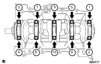
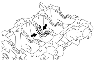
Using several steps, uniformly loosen and remove the 10 crankshaft bearing cap bolts with a 12 mm socket wrench for 12 pointed head in the sequence shown in the illustration.
-
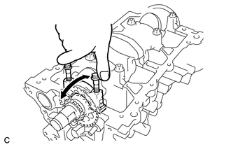
Using the 2 removed crankshaft bearing cap bolts, remove the 5 crankshaft bearing caps.
Tech Tips
-
Keep each No. 2 crankshaft bearing and crankshaft bearing cap as a set.
-
Arrange the removed parts in the correct order.
-
-
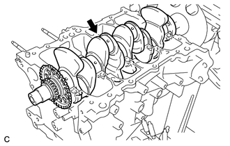
Remove the crankshaft from the cylinder block.
-
-
REMOVE UPPER CRANKSHAFT THRUST WASHER
-
Remove the 2 upper crankshaft thrust washers from the cylinder block.
Tech Tips
Arrange the removed parts in the correct order.
-
-
REMOVE CRANKSHAFT BEARING
-
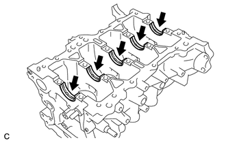
Remove the 5 upper crankshaft bearings from the cylinder block.
Tech Tips
Arrange the removed parts in the correct order.
-
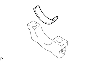
Remove the 5 lower crankshaft bearings from the crankshaft bearing cap.
Tech Tips
Arrange the removed parts in the correct order.
-
-
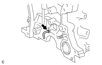
REMOVE WATER BY-PASS HOSE UNION
-
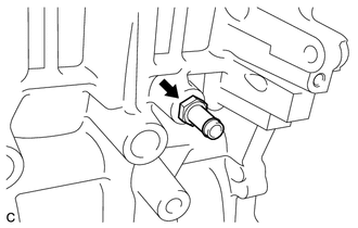
Using a 17 mm deep socket wrench, remove the water by-pass hose union from the cylinder block.
-
-
REMOVE OIL JET
-
Remove the oil jet from the cylinder block.
-