CYLINDER HEAD REPLACEMENT

PROCEDURE
-
REPLACE STUD BOLT
Tech Tips
If any of the stud bolts is deformed or the threads are damaged, replace it.
-
Using an E5 and E7 "TORX" socket wrench, replace the stud bolts.
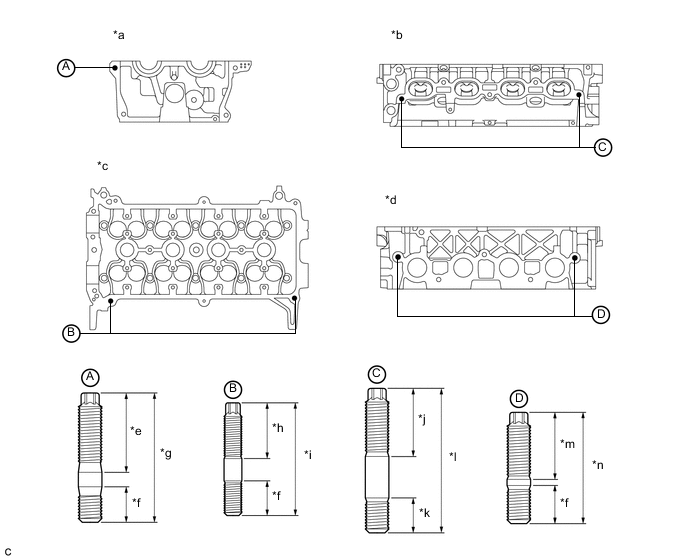
Text in Illustration *a Timing Chain Cover Side *b Intake Manifold Side *c Upper Side *d Exhaust Manifold Side *e 26.5 mm (1.04 in.) *f 12.0 mm (0.472 in.) *g 43.5 mm (1.71 in.) *h 19.5 mm (0.768 in.) *i 38.5 mm (1.52 in.) *j 28.5 mm (1.12 in.) *k 13.0 mm (0.512 in.) *l 49.5 mm (1.95 in.) *m 22.5 mm (0.886 in.) *n 37.5 mm (1.48 in.) - Torque:
- Stud Bolt A
- 10 N*m { 102 kgf*cm, 7 ft.*lbf }
- Stud Bolt B
- 4.0 N*m { 41 kgf*cm, 35 in.*lbf }
- Stud Bolt C
- 10 N*m { 102 kgf*cm, 7 ft.*lbf }
- Stud Bolt D
- 9.0 N*m { 92 kgf*cm, 80 in.*lbf }
-
-
REPLACE STRAIGHT PIN
Tech Tips
If a straight pin is deformed or the threads are damaged, replace it.
-
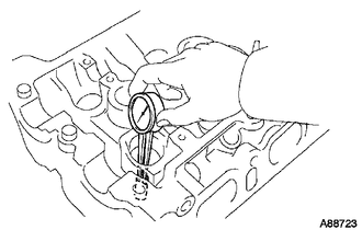
Remove the straight pins.
-
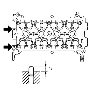
Text in Illustration *a Standard Protrusion Height Using a plastic hammer, tap in new straight pins to the specified protrusion height.
Standard protrusion height 4.5 to 5.5 mm (0.177 to 0.217 in.)
-
-
REPLACE INTAKE VALVE GUIDE BUSH
-
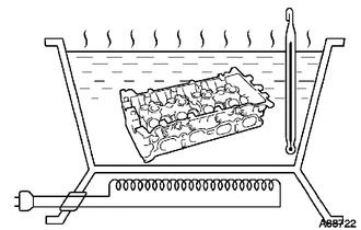
Heat the cylinder head to 80 to 100°C (176 to 212°F).
-
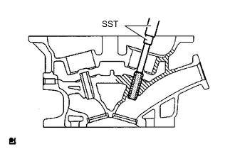
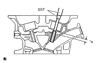
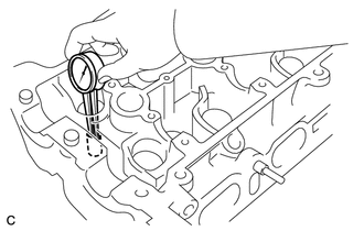
Using SST and a hammer, tap out the intake valve guide bush.
- SST
- 09201-10000 ( 09201-01050 )
- 09950-70010 ( 09951-07100 )
-
Using a caliper gauge, measure the bush bore diameter of the cylinder head sub-assembly.
Standard bore diameter Bush size Specified Condition STD 9.685 to 9.706 mm (0.381 to 0.382 in.) O/S 0.05 9.735 to 9.756 mm (0.383 to 0.384 in.) If the bush bore diameter of the cylinder head sub-assembly is greater than 9.706 mm (0.382 in.), machine the bush bore to the dimension of 9.735 to 9.756 mm (0.383 to 0.384 in.) to install an O/S 0.05 valve guide bush. If the bush bore diameter of the cylinder head is greater than 9.756 mm (0.384 in.), replace the cylinder head sub-assembly.
-
Heat the cylinder head sub-assembly to 80 to 100°C (176 to 212°F).
-
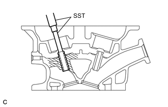
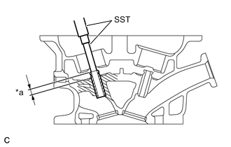
Text in Illustration *a Standard Protrusion Height Using SST and a hammer, tap a new intake valve guide bush into the specified protrusion height.
- SST
- 09201-10000 ( 09201-01050 )
- 09950-70010 ( 09951-07100 )
Standard protrusion height 9.0 to 9.4 mm (0.354 to 0.370 in.) -
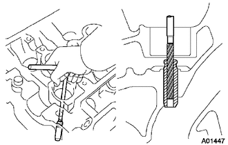
Using a sharp 5 mm reamer, ream the intake valve guide bush to obtain the standard specified clearance between the intake valve guide bush and the valve stem.
Standard oil clearance 0.025 to 0.060 mm (0.000984 to 0.00236 in.)
-
-
REPLACE EXHAUST VALVE GUIDE BUSH
-
Heat the cylinder head to 80 to 100°C (176 to 212°F).
-
Using SST and a hammer, tap out the exhaust valve guide bush.
- SST
- 09201-10000 ( 09201-01050 )
- 09950-70010 ( 09951-07100 )
-
Using a caliper gauge, measure the bush bore diameter of the cylinder head sub-assembly.
Standard bore diameter Bush size Specified Condition STD 9.685 to 9.706 mm (0.381 to 0.382 in.) O/S 0.05 9.735 to 9.756 mm (0.383 to 0.384 in.) If the bush bore diameter of the cylinder head sub-assembly is greater than 9.706 mm (0.382 in.), machine the bush bore to the dimension of 9.735 to 9.756 mm (0.383 to 0.384 in.) to install an O/S 0.05 valve guide bush. If the bush bore diameter of the cylinder head is greater than 9.756 mm (0.384 in.), replace the cylinder head sub-assembly.
-
Heat the cylinder head sub-assembly to 80 to 100°C (176 to 212°F).
-
Text in Illustration *a Standard Protrusion Height Using SST and a hammer, tap a new exhaust valve guide bush into the specified protrusion height.
- SST
- 09201-10000 ( 09201-01050 )
- 09950-70010 ( 09951-07100 )
Standard protrusion height 9.0 to 9.4 mm (0.354 to 0.370 in.) -
Using a sharp 5 mm reamer, ream the exhaust valve guide bush to obtain the standard specified clearance between the exhaust valve guide bush and the valve stem.
Standard oil clearance 0.030 to 0.065 mm (0.00118 to 0.00256 in.)
-