CYLINDER HEAD REASSEMBLY

PROCEDURE
-
INSTALL VALVE SPRING SEAT
-
Install the 16 valve spring seats to the cylinder head sub-assembly.
-
-
INSTALL VALVE STEM OIL SEAL
-
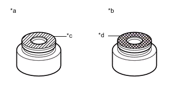
Text in Illustration *a Intake Side *b Exhaust Side *c Gray *d Black Apply a light coat of engine oil to a new valve stem oil seal.
Note
Pay close attention when installing the intake and exhaust valve stem oil seals. For example, installing the intake valve stem oil seal to the exhaust side or installing the exhaust valve stem oil seal to the intake side can cause installation problems later.
-
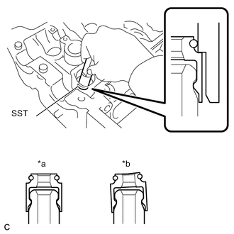
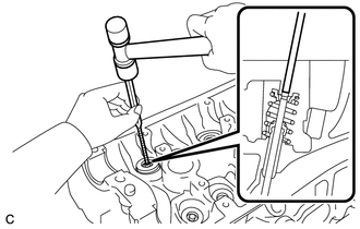
Text in Illustration *a CORRECT *b INCORRECT Using SST, push on the 16 valve stem oil seals.
- SST
- 09201-41020
Note
Failure to use SST will cause the seal to be damaged or improperly seated.
-
-
INSTALL INTAKE VALVE
-
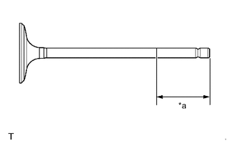
Text in Illustration *a 30 mm (1.18 in.) or more Sufficiently apply engine oil to the tip area of the intake valve shown in the illustration.
-
Install the 8 intake valves, 8 compression springs and 8 retainers to the cylinder head sub-assembly.
Note
Install the same parts in the same combination to their original locations.
-
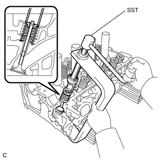
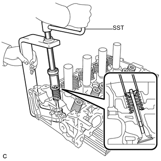
Using SST and wooden blocks, compress the compression spring and install the 8 retainer locks.
- SST
- 09202-70020 ( 09202-00010, 09202-01010, 09202-01020 )
-
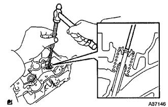
Using a pin punch and plastic hammer, lightly tap the valve stem tip to ensure a proper fit.
Note
Be careful not to damage the valve stem tip.
-
-
INSTALL EXHAUST VALVE
-
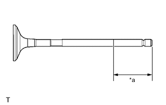
Text in Illustration *a 30 mm (1.18 in.) or more Sufficiently apply engine oil to the tip area of the exhaust valve shown in the illustration.
-
Install the 8 exhaust valves, 8 compression springs and 8 retainers to the cylinder head sub-assembly.
Note
Install the same parts in the same combination to their original locations.
-
Using SST and wooden blocks, compress the compression spring and install the 8 retainer locks.
- SST
- 09202-70020 ( 09202-00010, 09202-01010, 09202-01020 )
-
Using a pin punch and plastic hammer, lightly tap the valve stem tip to ensure a proper fit.
Note
Be careful not to damage the valve stem tip.
-
-
INSTALL VALVE LIFTER
-
Apply a light coat of engine oil to the valve lifters.
-
Install the 16 valve lifters.
Note
Install the same parts in the same combination to their original locations.
-
Check that the valve lifters rotate smoothly by hand.
-
-
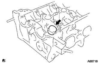
INSTALL OIL CONTROL VALVE FILTER
-
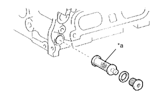
Text in Illustration *a Mesh Part Check that no foreign matter is on the mesh part of the oil control valve filter.
-
Using an 8 mm hexagon wrench, install the oil control valve filter with a new gasket and the straight screw plug.
- Torque:
- 30 N*m { 306 kgf*cm, 22 ft.*lbf }
-
-
INSTALL TAPER SCREW PLUG
-
Install a new gasket to the taper screw plug.
-
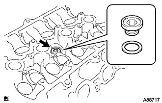
Using a 10 mm hexagon wrench, install the taper screw plug.
- Torque:
- 44 N*m { 449 kgf*cm, 32 ft.*lbf }
-